Week 9 Challenge
Objective: To build an energy management strategy model to distribute the positive power demand among Batteries, ultracapacitors and Fuel Cells.
Theory:
In the electric powertrain model, three power source components were added. Fuel cell stack, battery and UC are all capable of proving power. So the energy management strategy is like a supervisor that decides which component should provide the power. It is also responsible for maintaining the SOC of the components to its nominal SOC level. The energy management strategy needs to consider the operating limit of the components.
The aim of the energy management strategy must be to optimize performance and minimize fuel consumption. So it must also know the most efficient operating points apart from the limits. An industrial-level EMS should also have some fault reactions if faults occur. To create an efficient distribution of power demand to energy sources on board, an understanding of components is important. The EMS should ensure to work for maximizing the life of the battery. The fuel cell should be operated to reduce hydrogen consumption and provide sufficient power. The UC, being very robust must be efficiently used in areas where other components lack.
1. Battery:
The parameter that affects the battery life related to EMS is its charge/discharge cycles with some loss when static. The C rate of the battery is also important when it comes to battery life. The C rate also affects the temperature which contributes towards degradation. The degradation occurs in the form of the loss of lithium.
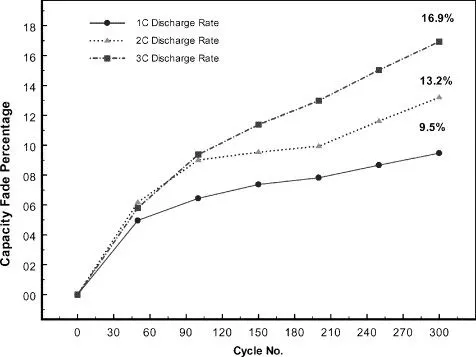
The C rate is a measure of the rate at which the battery is being discharged or charged. If the C rate is low, the current drawn per second is low. This will result in a lower power operating window. When the battery is charged daily, it loses relative capacity. The battery when operated between 20% - 60%, the loss is the least. Some power is lost when the battery is not in use.
2. Fuel Cell:
The important parameter to keep in mind in terms of EMS for the fuel cells is the losses. The system efficiency map is an important parameter. The three kinds of losses below define the output and fuel efficiency of the fuel cell:
- Activation loss
- Ohmic loss
- Mass concentration loss
The fuel cell polarization curve provides the conditions for EMS. The operation must be within the ohmic loss region.
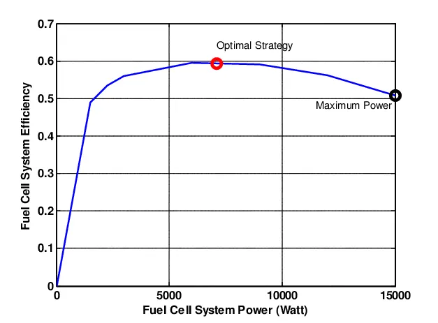
- At low load, FCS efficiency is very low due to the operation of the air compressor, cooling system and humidifier.
- The FCS efficiency is high at medium load.
- At high load, efficiency is again low as FC current increases.
3. Ultracapacitor:
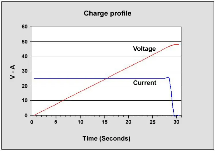
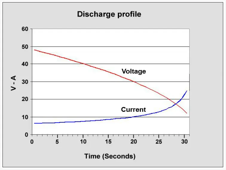
Certain parameters should be considered for selecting the UC that would be part of the ESS. The maximum charge voltage should be decided based on DC-DC used. The minimum voltage should be decided based on bus voltage and DC-DC. The power or current required to be delivered by the UC to attain the vehicle characteristics. The voltage of a UC increases linearly when charged and currently drops. However, exceeding the voltage of UC beyond a limit can damage the UC.
Simulink Model:
The Energy Management technique is followed based on the following criteria:
| Power Demand | Condition | Source |
| 0 - 9999 |
If UC_SOC > 35% If UC_SOC < 35% |
Ultracapacitor Fuel Cell |
| 10000 - 22999 |
If Battery_SOC > 35% If Battery_SOC < 35% |
Battery Fuel Cell |
| 23000 - 54999 | No condition | Fuel Cell |
| 55000 and above |
If UC_SOC > 35% If UC_SOC < 35% |
Ultracapacitor Fuel Cell |
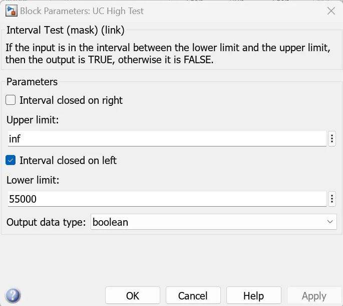
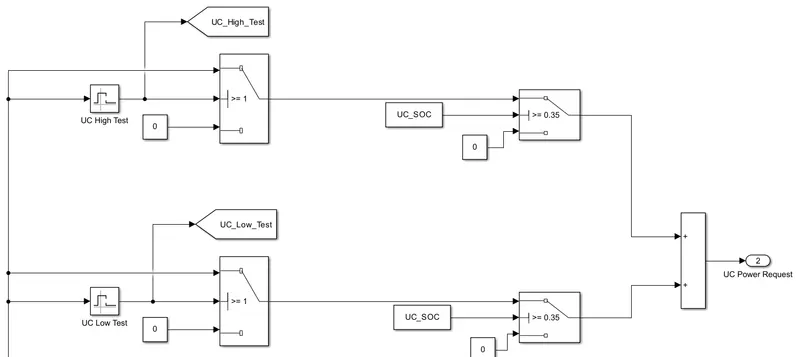
1. Simulink for power demand > 55000
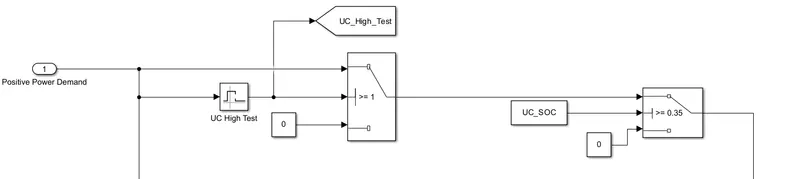
When the power is above 55000, the first switch will send the input power to the second switch and when the UC_SOC > 35%, the second switch will send the power as output.
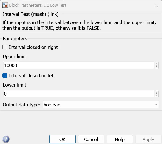
2. Simulink for power demand between 0 and 10000
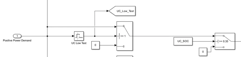
When the power is between 0 to 10000, the first switch will send the input power to the second switch and when the UC_SOC > 35%, the second switch will send the power as output.
Add both the outputs because one output will be zero when the other is having value and both the limits are supplied by Ultracapacitor.
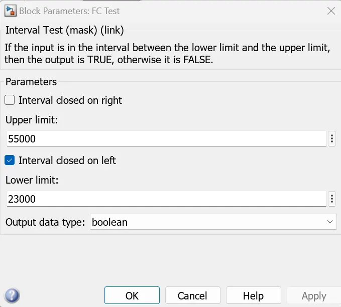
3. Simulink for power demand between 23000 and 55000
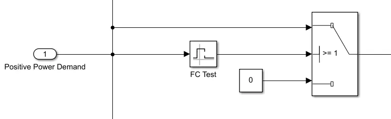
The power demand between 23000 and 55000 is supplied by the Fuel Cell. Here, we need not use a second switch because we are not going to check the SOC of the Fuel Cell as the fuel cell does not store any energy.
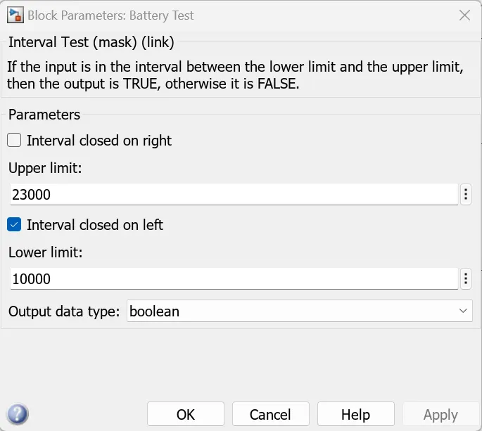
4. Simulink for power demand between 10000 and 23000
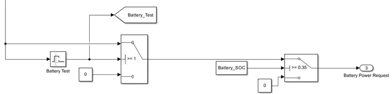
When the input power is between 10000 to 23000 and the Battery_SOC > 35%, this power demand will be supplied by the Battery.
Fuel Cell backup for ultracapacitor
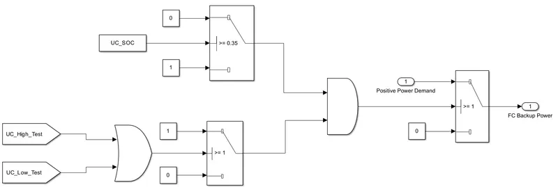
If the power demands supplied by the ultracapacitor are TRUE and if the UC_SOC is less than 35%, the fuel cell must be acting as a backup.
Fuel Cell backup for Battery
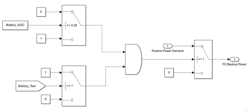
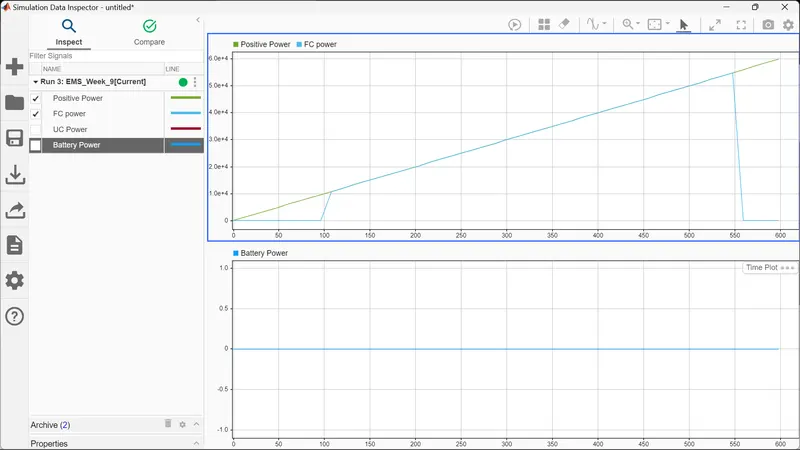
If the power demand supplied by the battery is TRUE and if the Battery_SOC < 35%, the fuel cell must be acting as backup.
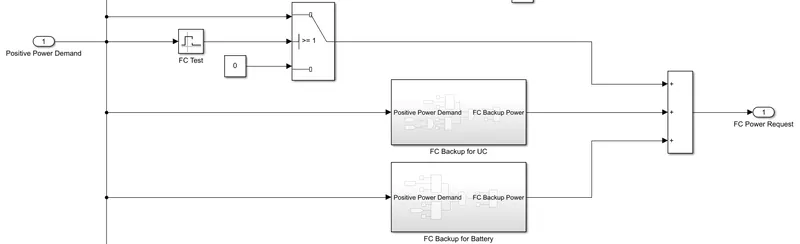
After completing both the backup add both the outputs of the fuel cell because the fuel cell will provide power for the range between 23000 & 55000 and also act as a backup for both the ultracapacitor and battery.
Output:
1.

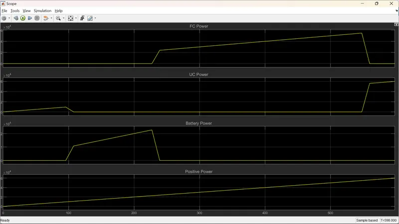
Output of UC Power demand when the UC_SOC > 35%
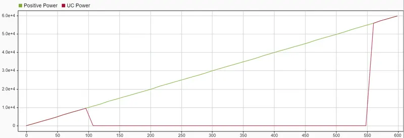
From the graph, it is clear that the Ultracapacitor will supply all the power between 0 to 10000 and 55000 & above when its SOC > 35%.
Output for battery power demand when the Battery_SOC > 35%.
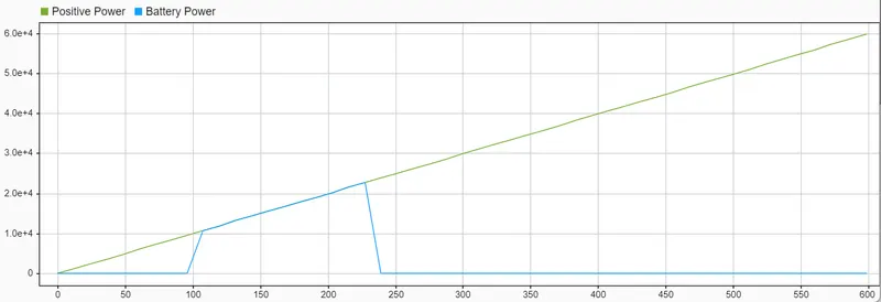
From the graph, it is clear that the battery will supply all the power between 10000 to 23000 when SOC > 35%.
Output for fuel cell power demand
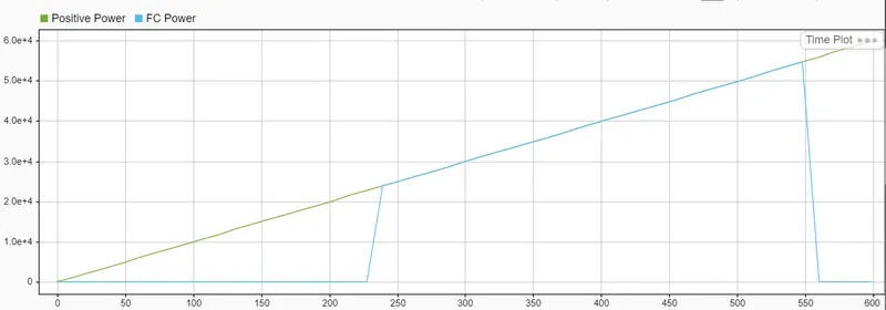
From the graph, it is clear that the fuel cell will supply all the power between 23000 & 55000.
2.

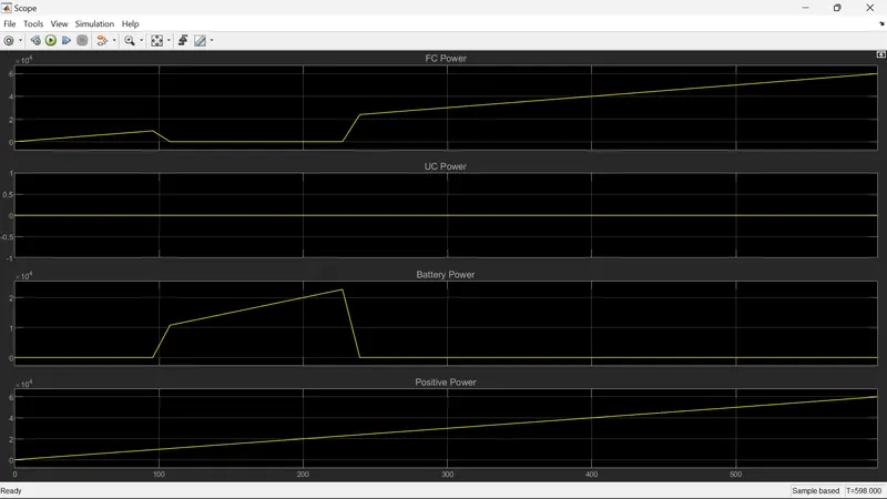
Output for Ultracapacitor power demand when the SOC_UC < 35%.
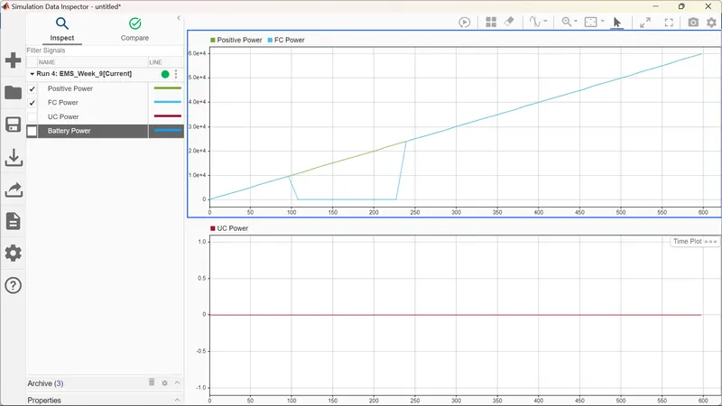
From the graph, it is clear that when the UC_SOC < 35% the Ultracapacitor should not supply any power, but since the fuel cell act as backup, all the power that should be supplied by Ultracapacitor is supplied by the Fuel Cell.
3.

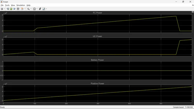
Output for battery power demand when the Battery_SOC < 35%
Result:
It is clear that when the UC_SOC & Battery_SOC are greater than 35% the Ultracapacitor will supply when the power demand is between 0 to 10000 and 55000 & above, the battery will supply when the power demand is between 10000 to 23000, the fuel cell will supply when the power demand is between 23000 to 55000.
Conclusion:
With an understanding of the operations of each component, an appropriate usage scenario can be defined. The battery lives longer with a lower C rate, so it is best suited for constant low power demand. The fuel cell is the most efficient for medium power demand. The UC is fairly robust and can be used during the peak power demand to reduce the load on other components.
The torque demand has to be converted to power. Positive power and negative power are separated. Positive power is categorized between low, medium and high. Then an appropriate source is chosen. Negative power is the regenerative power. When the vehicle is decelerating or when the driver pushes the brake pedal, the regenerative energy charges the battery or UC.
For positive power, some fail-safe strategy also needs to be created. If the SOC is low and the battery/UC can't support it, then FCS should be used. There should not be a situation where no source is providing power.