Project 5
AIM: To calculate the voltage, current, and SOC of a 10-cell series lithium-ion battery pack model and observe the thermal effect and life cycle performance of cells.
Objectives:
- Simulate the model and observe the thermal effect at various temperatures and charge-discharge rates.
- Similarly, observe the life cycle performance at various temperatures and charge-discharge rates.
Battery Pack:
A battery pack is a set of any number of identical individual cells. They may be configured in a series, parallel, or a mixture of both to deliver the desired voltage, capacity, or power density. Rechargeable battery packs often contain a temperature sensor, which the battery charger uses to detect the end of charging. Interconnects are also found in batteries as they are the part that connects each cell, as per our requirement battery connection configuration made. If we want more voltage than the individual cell then the series connection is made and if we want more current capacity then connect cells in a parallel manner.
Simulink Model:
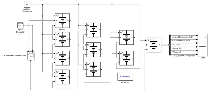
- Signal Generator: The Signal Generator block can produce one of four different waveforms: sine, square, sawtooth, and random. We can express signal parameters in hertz or radians per second. For this model, I used a square waveform with -Ia variable as amplitude and 2π rad/sec frequency. This signal is provided to the current controlled source.
- Controlled Current Source: The Controlled Current Source block converts the Simulink input signal into an equivalent current source. The generated current is driven by the input signal of the block. The positive current direction is shown by the arrow in the block icon. We can initialize the Controlled Current Source block with a specific AC or DC. If you want to start the simulation in a steady state, the block input must be connected to a signal starting as a sinusoidal or DC waveform corresponding to the initial values. For this model, I used the default value.
- Battery: The Battery block implements a generic dynamic model that represents the most popular types of rechargeable batteries. This model enables the temperature effects and aging effects options. So cell nominal voltage is 7.2 V, Capacity 5.4 Ah, initial SOC 100%, in aging section aging model aging sample time is 20 sec, aging characteristic at cell ambient temperature of cell 25°C and nominal charge and discharge current take as Ia variable (I take variable because every simulating time with the different current value, it is a tedious process to change the all cells charge-discharge current) which is similar to the input current signal. And all other parameters are default values. So now our battery pack voltage is 72 V and capacity is 5.4 Ah.
So all these blocks are connected as per shown in the above model figure. And this model runs for 10 sec, so we can charge and discharge the battery pack multiple times.
Result:
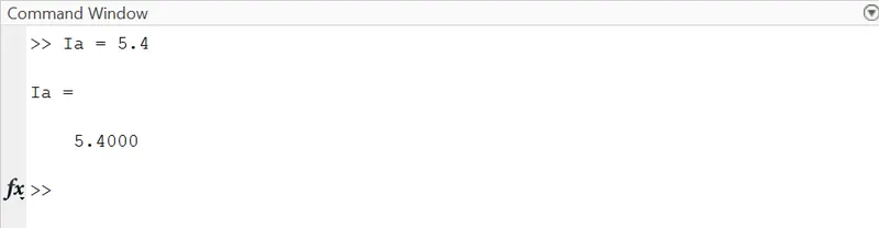
So this Simulink model simulates multiple times at various ambient temperatures and different charge-discharge current rates. The ambient temperature varies by changing the ambient temperature constant block and the charge-discharge value varies by using the MATLAB command window as shown in the below figure.
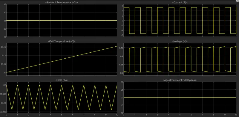
Case 1: Ia = 5.4 A and Ambient Temperature = 25 degree C
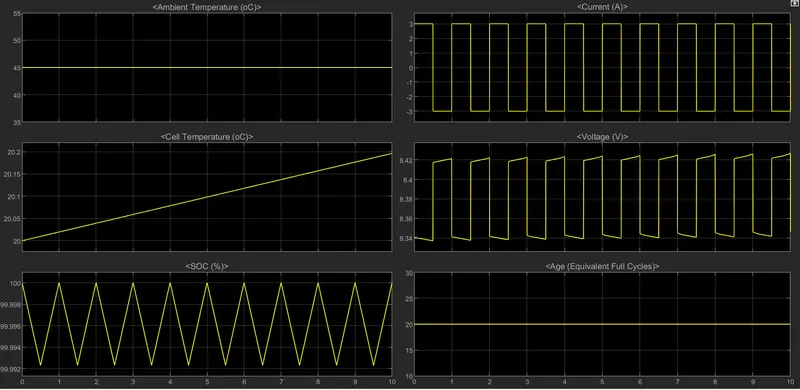
Case 2: Ia = 3 A and Ambient Temperature = 45 degree C

Conclusion:
From this different case study, I conclude that:
- When the ambient temperature increases then cell temperature is increased.
- The age of the battery remains the same, SOC is not able to charge or discharge completely, the cell temperature is less and in the voltages spikes are present.