Project 3
AIM: To design and simulate Buck converter for Auxiliary load in EV.
Given:
Let us assume that the switching frequency is 50kHz, i.e., f = 50kHz.
Input voltage, Vdc = 48 V
Output voltage, Vo = 12 V
Load current, iL = 10 A
Vo = D * Vdc
12 = D * 48 , D = 12/48 = 1/4 = 0.25
Duty Cycle, D = 0.25
Vout = Iout * R
R = Vout / Iout = 12 / 10 = 1.2 Ω
Resistance of the load, R = 1.2 Ω.
Let us assume that the inductor current ripple is less than 30% of the average inductor current and the output voltage ripple of the capacitor is less than 5%.
Now,
△iL = 30% of Iout
= 0.3 * 10
= 3 A
L = Vout / (f * △iL)
= 12 / (50x10^3 * 3)
= 0.08 mH
Inductance, L = 0.08 mH.
Cout = (1 - D) / [8*L*f^2*(△Vo/Vo)]
= (1 - 0.25) / [8*0.08x10^(-3)*50*50*0.05]
= 9.375 μF
Capacitance, Cout = 9.375 μF
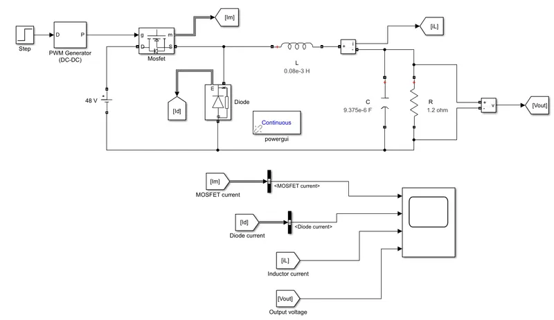
Now, we will add these values to the respective blocks in the Simulink as shown below:
Simulink Model:
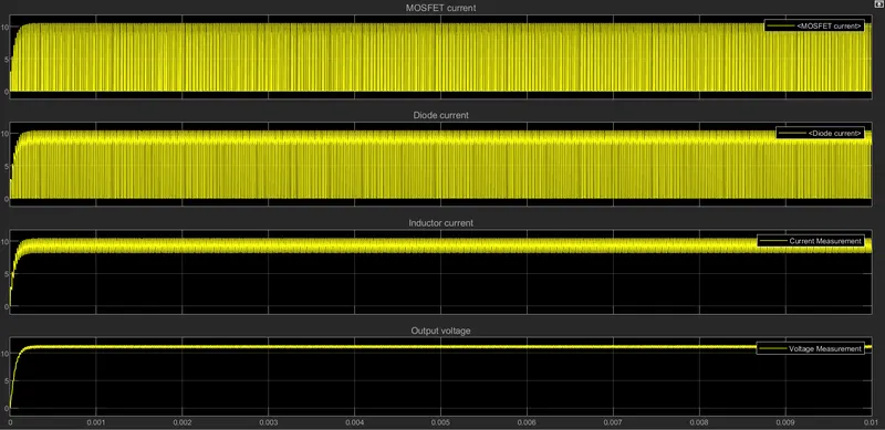
Result:
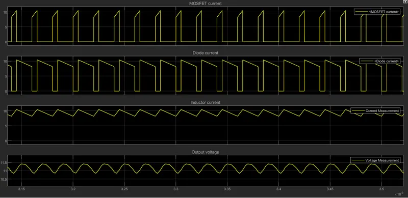
Result: After zooming in closer.
Conclusion:
We have designed and simulated the buck converter for Auxilary load in EV with the calculations of Duty Ratio, Resistance in load, Inductance, and Capacitance.