Week 9 Challenge
Aim : To calculate the wave load on the bridge superstructure by using following data.
Given data :
- Width of the deck slab is 9 m
- Span of bridge is 12 m
- Maximum crest elevation is 3 m
- I girder,
height is 1.7 m, width 2.5 m, thickness of eb and flange is 0.5 m
- Thickness of deck slab is 2 m
- R = 5 , Cva = 3, Cr = 0.4
Theory :
Waves are caused by disturbance of the water surface.
When the wind blows on the sea , waves occurs according to the intensity of the wind and generate a force on the any bridge sub structure like piers and abutments.
Calculation:
- Δ Zh = ηmax – centroid of girder
= 3 – ( 1.7 / 2 )
Δ Zh = 2.15 m.
- Δ Zv = ηmax - elevation of bottom deck
= 3 – 2
Δ Zv = 1 m
- Number of girder , N = 3
- Vertical load, Fv = r x Δ Zv x Av
= 5 x 1 x ( 9 x ( 1.7/2))
Fv = 38.25 KN
- Horizontal load, Fh = r x Δ Zh x Ah
= 5 x 2.15 x ( 3.7 x 12))
Fh = 477.3 KN
- Max vertical load , Fv max = Cva x Fv
= 3 x 38.25
Fv max = 114.75 KN
- Max horizontal load , Fh max =[ 1 + Cr ( N – 1 ) ] Cva x Fh
= [ 1 + 0.4 ( 3 – 1 )] 3 x 477.3
Fh max = 1622.82 KN
Aim : To prepare the model in a STAAD Pro and perform the analysis and justify with the results.
Theory : The general steps to be create a STAAD Pro model is given below,
Step 1 : Create the nodes by using the nodes cursor.
Step 2 : Joining the nodes by using the respective beam plate cursor.
Step 3 : Supports given to the nodes whether its pinned or fixed or any other custom supports
Step 4 : specifications given to the respective beams plates
Step 5 : Assign the dead load as per calculation
Step 6 : Save the model and perform the analysis
Step 7 : The results are obtained and discuss with the results
Step 8: Take the print out of report of necessary results.
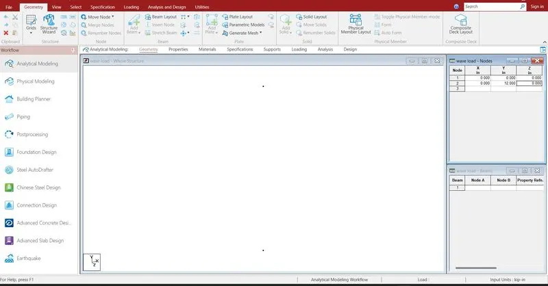
Creating the nodes by using node cursor.
Open the STAAD Pro window > Select > Node cursor > enter the value with respect to X Y Z axis > click enter
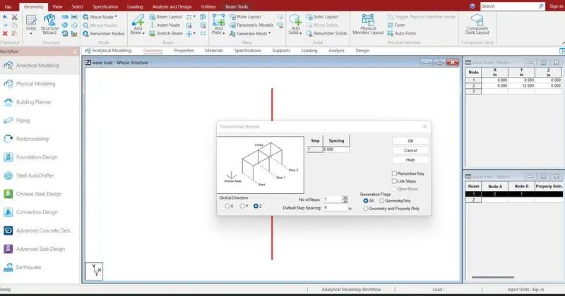
Join the nodes by using beam cursor.
Select > beam cursor > join by dragging the mouse or enter the node numbers > click enter
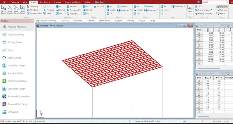
By using nodes and translation repeat plates mesh like structures are created.
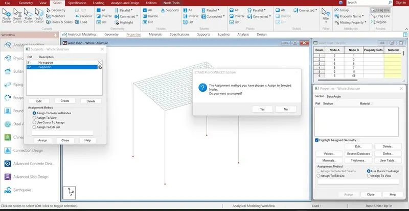
Supports are given to the respective nodes.
Specifications > Supports > select the supports > click enter
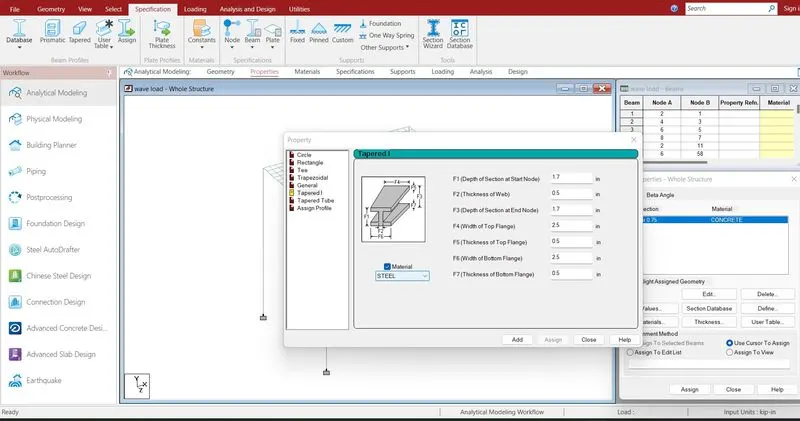
Assigning the properties to the beam .
Specification > Prismatic > Rectangle > enter dimensions > select the beam > assign the properties to selected beams.
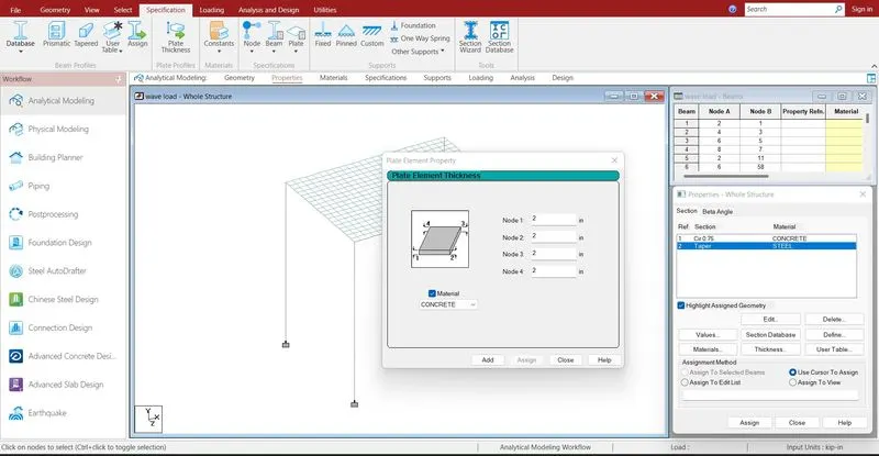
Plate thickness defined
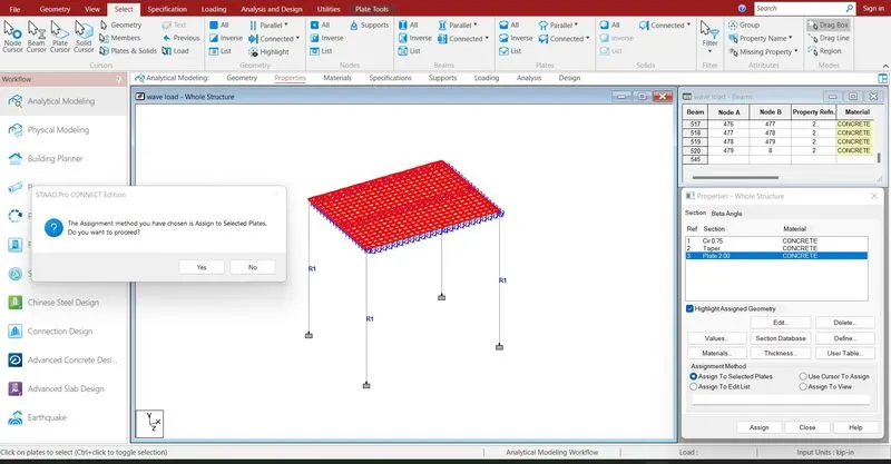
Plate properties are defined.
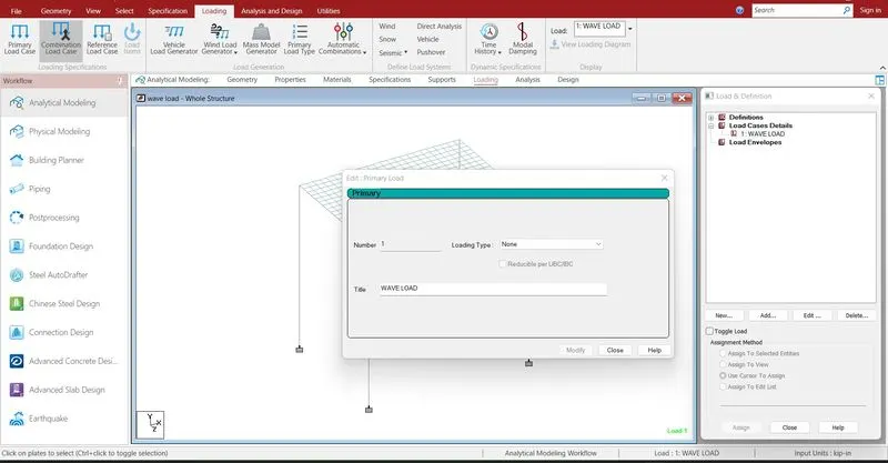
Defining the load cases .
Loading > Load case detail > select load > Add
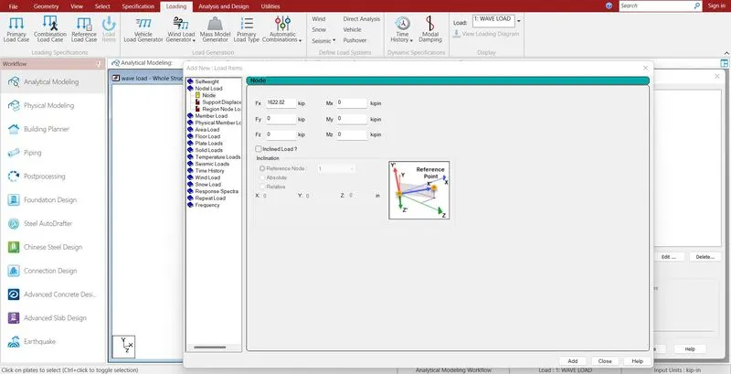
Add > nodal load X direction > enter value > ok
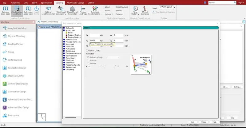
Add > nodal load Y direction > enter value > ok
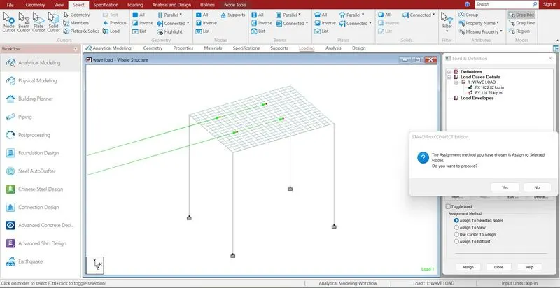
Select the defined load > select the node > Assign to selected node > click enter
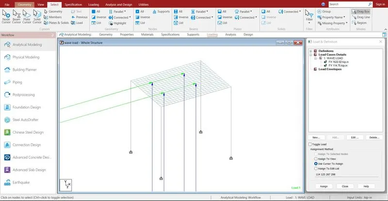
Select the defined load > select the node > Assign to selected node > click enter
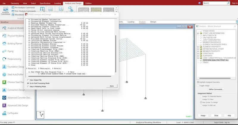
Run analysis > go to post processing mode > Results
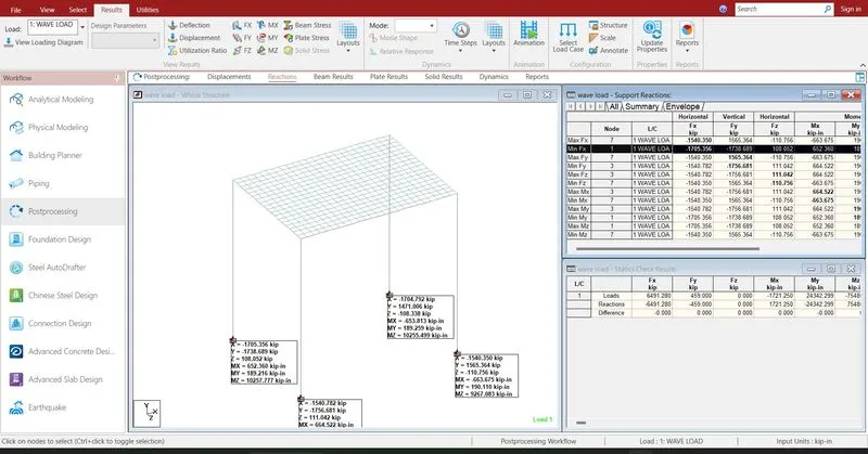
The reactions are generated at the end of the nodes .the reaction value is 6491.28 KN in X direction
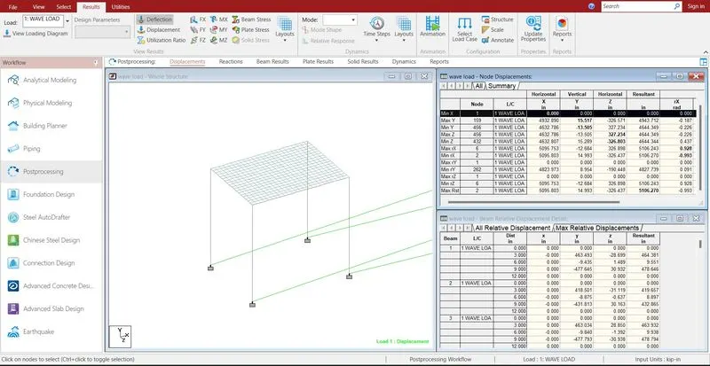
- The maximum deflection in X direction is 5096.145mm
- The minimum deflection in X direction is 0 mm
- The maximum deflection in Y direction is 4932.89 mm
- The minimum deflection in Y direction is 4632.786 mm
- The maximum deflection in Z direction is 4632.786 mm
- The minimum deflection in Z direction is 4632.807mm
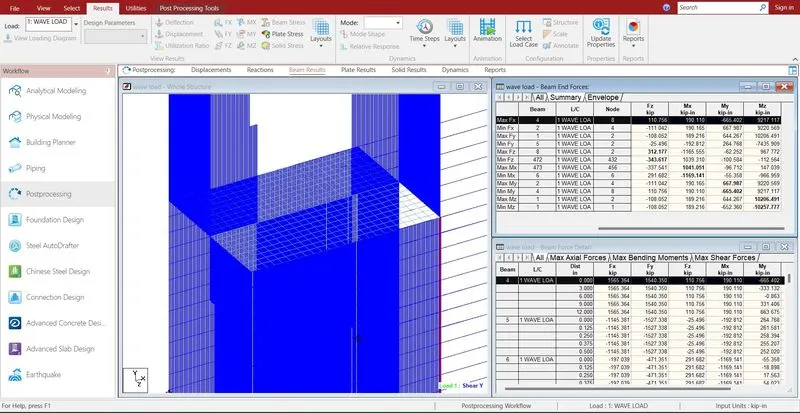
- The maximum shear force in X direction is 1565.364 KN
- The minimum shear force in X direction is -1756.681 KN
- The maximum shear force in Y direction is 1705.356 KN
- The minimum shear force in Y direction is -1527.338 KN
- The maximum shear force in Z direction is 312.177 KN
- The minimum shear force in Z direction is -343.617 KN
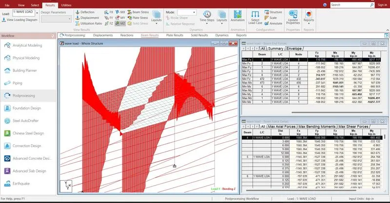
- The maximum bending moment in X direction is 1041.051 KN-m
- The minimum bending moment in X direction is -1169.141 KN-m
- The maximum bending moment in Y direction is 667.987 KN-m
- The minimum bending moment in Y direction is -665.402 KN-m
- The maximum bending moment in Z direction is 10206.491 KN-m
- The minimum bending moment in Z direction is - 10257.777 KN-m
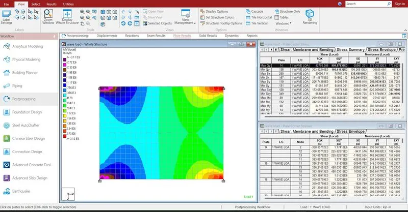
- The maximum shear stress in y direction is 138.48 KN/m2
- The minimum shear stress in y direction is -143.241 KN/m2
- Reports are taken printout which ever is necessary by using report
- In the report option we obtain the results of section forces, displacement, reactions, plate
- The exact report is to be taken further move to design