Week 9 Challenge
Energy Management system
# AIM
To design the energy management strategy model with battery, ultracapacitor and fuel cell for positive power and to distribute the power demand among these components.
# THEORY
Energy Management Strategy:
Energy management strategies are the algorithms that decide the power split between the engine and motor in order to improve the fuel economy and optimize the performance of HEVs. An energy management strategy is mainly required for the hybrid electric vehicle which uses more than one energy-storing element. It is mainly used to distribute the load demand among the energy storage elements to operate the vehicle in the high-efficiency mode. Every energy storage element has the optimum operating range where they can deliver power at high efficiency. If the battery, fuel cell, and ultracapacitor are used in a vehicle as energy storage elements. Then it is a high priority to use the energy management system.
The battery cannot be able to supply high power for a long time and sudden peak load. For high power demand, the battery pack size and cost also increase. If the battery is used to supply high power for a long time, it leads to degradation of the battery. It is not a favorable condition. Hence battery can be operated for low power demands more efficiently.
Ultracapacitors cannot be used efficiently to deliver low power demands and medium power demands for a long time. Ultracapacitors complement a primary energy source that cannot repeatedly provide quick bursts of power, such as an internal combustion engine, fuel cell or battery. But it can be efficiently used to meet the sudden high peak load and to use the high regenerative current for a charge.
Fuel cells only be operated in the optimum operating zone for high efficiency. If it is operated below the operating range (low power region) it is in an activation loss region where the efficiency is very less. If the fuel cells are operated above the optimum operating area in the mass concentration loss region (high power region) the efficiency is very less. Only if the fuel cells are operating in the ohmic loss region (medium power region) the efficiency is high. Hence fuel cells are used to deliver medium power loads.
Flow chart:
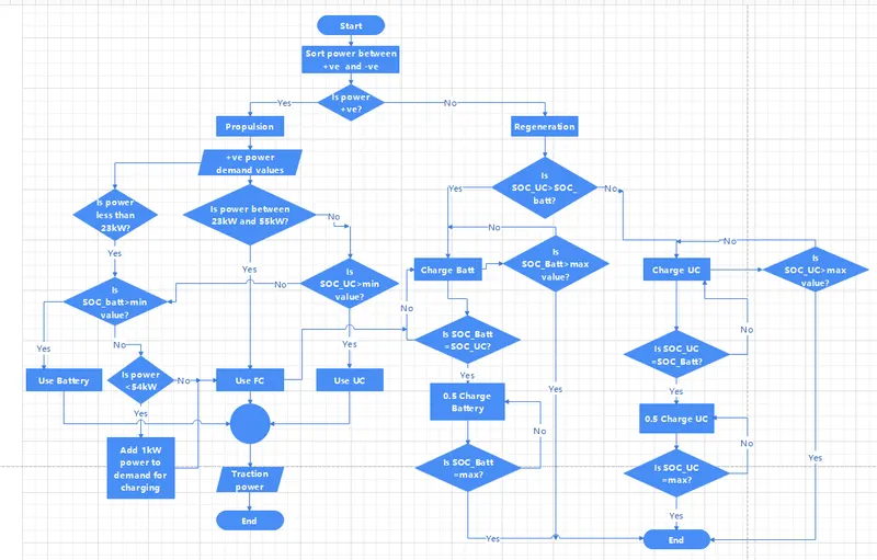
The above flow chart explains the condition for load sharing by energy management systems. It is used to design the Simulink model for energy management systems.
Software used:
- MATLAB/ Simulink
Blocks Used:
- Constant
- Signal builder
- Switch
- Interval test
- Gain
- Greater than
- Equal to
- AND
- OR
- Add
- Goto
- From
- In
- Out
- Scope
# SIMULINK MODEL
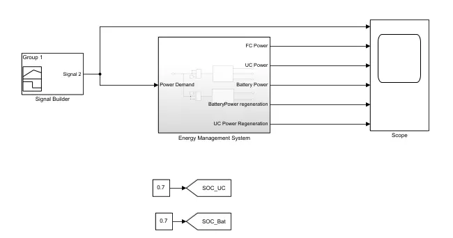
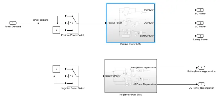
Procedure:
- The input to the energy management system is power demand which is provided by the powertrain.
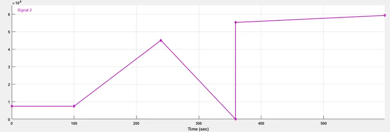
- Here for simplification and understanding, we use the signal builder for the power demand.
Signal Builder:
- The SOC of ultracapacitor and battery can be given manually to analyze the result and for better understanding of the working algorithm.
- If the power demand is positive, that is used for propulsion.
- The load demand sharing algorithm has to be used to deliver the load.
Positive power Subsystem:
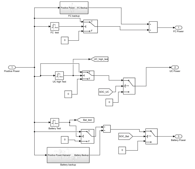
- The operating range for the fuel cell is 23kW to 55kW. It is derived from the polarization curve.
- The active area of the fuel cell is 420cm^2.
- The operating range starts from the current density of 0.24A/cm^2 and ends at 0.76A/cm^2.
- The average voltage of each cell is 0.6V.
- If 380 cells are used in series, then the total voltage is 380*0.6 = 228V.
- Lower limit of current = 420*0.24 = 100.8A
- Upper limit of current = 420*0.76 = 319A
- Lower power limit = 228*100.8 = 22.9kW
- Upper power limit = 228*319 = 72.7kW
- At 72.7kW, the efficiency is less.
- So the upper power limit is taken as 55kW for high efficiency.
- If the power demand is low i.e., in our case if it is less than 23kW and if SOC is greater than the minimum value of the battery then this power has to be delivered by the battery.
Battery backup subsystem:
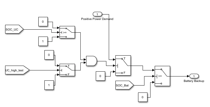
- If the SOC is less than minimum value, then this power has to be delivered by fuel cell.
Fuel cell backup Subsystem:
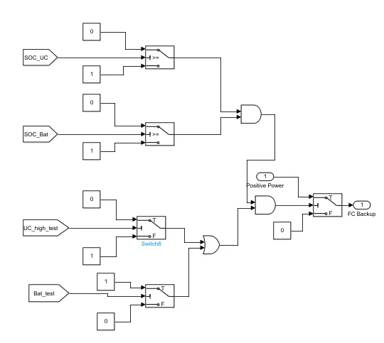
- If the power demand is between 23kW and 55kW then this power can be delivered by the fuel cell.
- If the power demand is above 55kW and if the SOC of the ultracapacitor is greater than the minimum value then this power has to be delivered by the ultracapacitor.
- If the SOC of the Ultracapacitor is less than the minimum value, then this power has to be met by the battery.
- And if both SOC of the battery and ultracapacitor is less than the minimum value then that power has to be delivered by the fuel cell.
- For the negative power i.e., regenerative braking, if the SOC of the ultracapacitor is greater than battery then the regenerative power is used to charge the battery.
# RESULT
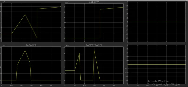
If SOC_UC = SOC_batt:
Summary:
From the above plot, if both SOC_UC and SOC_batt are equal, then the negative power is shared equally between the ultracapacitor and battery for charging. And the positive power is shared among the components according to the energy-sharing algorithm. The low power (0kW-23kW) is met by a battery, medium power (23kW-55kW) is met by a fuel cell and peak power (>55kW) is met by an ultracapacitor.
# CONCLUSION
Completed the energy management strategy model with battery, UC, and fuel cell for the positive power and distributed the power demand among these components.