Week -2
1) PART 1
#AIM
Make a Simulink model of a Doorbell using a solenoid block
# OBJECTIVE
To create a situation where the switch is closed for 2 seconds and then released. Observe the physical movement of the plunger.
# THEORY
* Solenoid
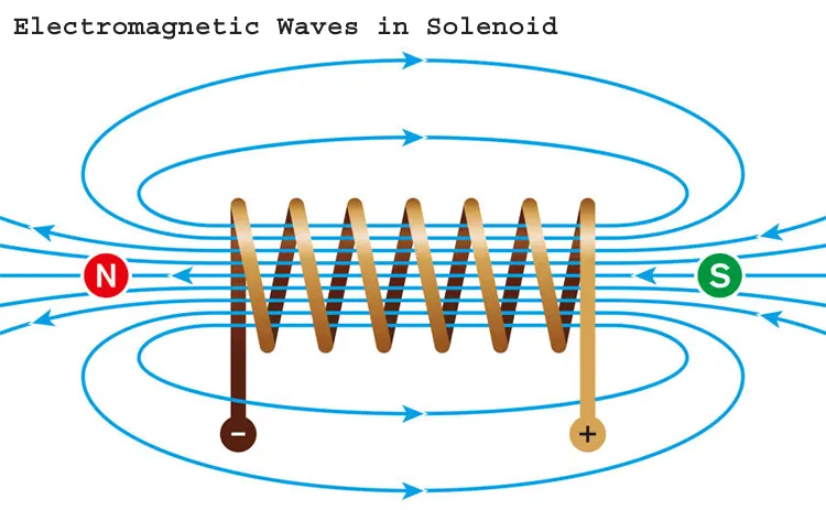
Fig 1: Solenoid
- A solenoid is a device comprised of a coil of wire, housing, and a moveable plunger (armature). When an electrical current is introduced, a magnetic field forms around the coil which draws the plunger in. More simply, solenoid converts electrical energy into mechanical work.
- The coil is made of many turns of tightly wound copper wire. When an electrical current flows through the wire, a strong magnetic field/flux is created.
- The housing usually made of iron or steel surrounds the coil concentrating the magnetic field generated by the coil.
- The plunger is attracted to the stop through the concentration of the magnetic field providing the mechanical force to do work.
* Doorbell
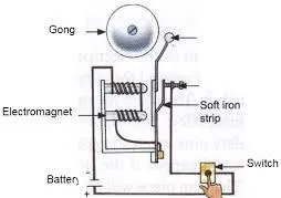
Fig 2: Doorbell
- The doorbell is a device having mechanical and electrical components, that produces the sound by pressing the switch.
- When the switch is pressed, the circuit loop is complete which causes the current to flow through the circuit.
- while passing the current through the solenoid it generates the electromagnet at desired space, which allows the plunger to move, due to which it hits the bell and produces sound.
# SIMULATION
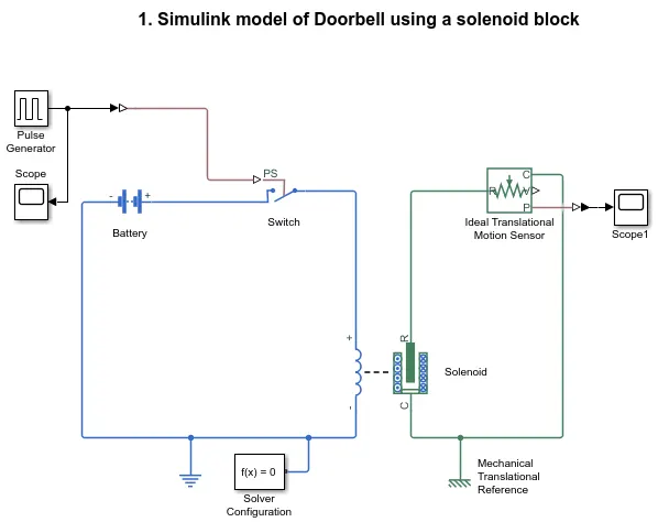
Fig 3: Simulink Model of Doorbell using Solenoid
*Block Diagram Explanations
- Pulse generator: Pulse Generator block generates square wave pulses at regular intervals. The block waveform parameters, Amplitude, Pulse Width, Period, and Phase delay, determine the shape of the output waveform.
- Battery: It gives the power supply to the close loop.
- Switch: Switch is controlled by an external physical signal.
- Solenoid: Electrical characteristics and generated force of the solenoid.
- Ideal translational Motion Sensor: It is a motion sensor in mechanical translational systems.
- PS-Simulinik Converter: Converts physical signal into Simulink output signal.
- Simulink-PS Converter: Converts the Simulink input signal into a physical signal.
- Electrical reference: Reference Connection to electrical ground.
- Mechanical Translational References: Reference connection for mechanical translational ports
- Scope: it displays the signals generated during simulation.
# SIMULATION RESULTS
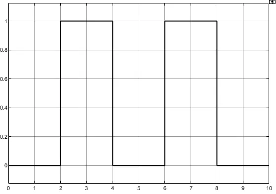
Fig 4:Input Waveform
- During 0s-2s the pulse generator waveform is zero because here the phase delay is 2s and the phase width is 50% and the period is 4s.
- During 2s-4s the pulse generator generates a square wave with amplitude 1.
- By using these conditions we can make the doorbell in its initial position for 2s and then move for the next 2s.
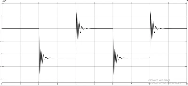 Fig 5: Output Waveform
- From the graph, it is clear that the plunger is moving from its initial position with a time delay of 2s.
- During 0s-2s, the switch is open that is pulse generator input is zero, therefore it remains in its initial position.
- During 2s-4s, the switch is closed and the square input of the pulse generator is given, then it rings the bell by hitting the plunger
# CONCLUSION
Created a situation where the switch is closed for 2 seconds and then released using a pulse generator. When the switch is closed the electromagnet receives electrical power from the battery and pulls the metal arm to hit the bell producing sound. The motion of the plunger was simulated and recorded and plotted by using an ideal motion sensor and scope.
2) PART 2
#AIM
By using a thermistor sense the temperature of the heater and turn on or turn off the fan as per conditions.
#OBJECTIVE
Use a thermistor to sense the temperature of a heater & turn on or turn off the fan as per the below conditions:
- Temperature source: 20 °C from 0 to 10 seconds, 27 °C from 10 to 30 seconds, and 23 °C from 30 to 50 seconds.
- Fan conditions: ON if the temperature above 25 °C, OFF otherwise
#THEORY
* Thermistor
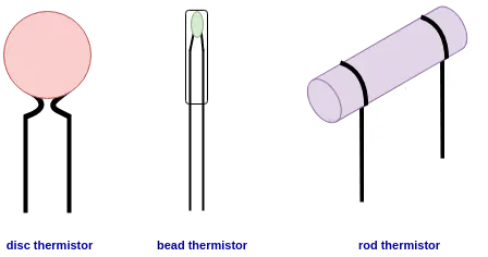
Fig 6 : Thermistors
- The thermistor works on the simple principle of change in the resistance due to a change in temperature.
- When the ambient temperature changes, thermistor starts self-heating its elements. its resistance value is changed with respect to the change in the temperature.
- This change depends on the type of the thermistor used. NTC & PTC are the types of thermistors.
- NTC stands for Negative Temperature coefficient. The resistance of an NTC will decrease with the increasing temperature in a non-linear manner.
- PTC thermistors are Positive Temperature Coefficient resistors. The resistance of PTC will increase with increasing temperature in a non-linear manner.
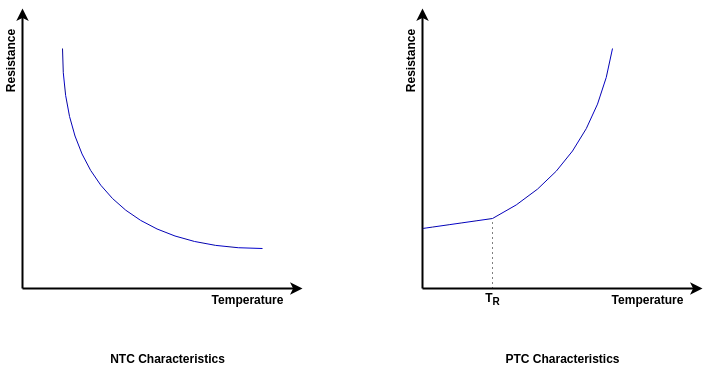
Fig 6: NTC &PTC Characteristics
#SIMULATION
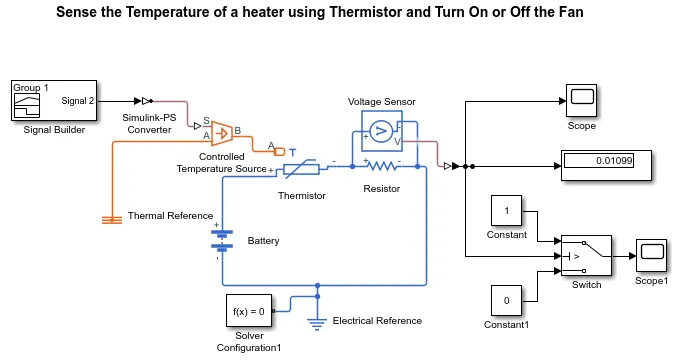
Fig 7: Simulation Model of Fan controlled by Thermistor
- Signal Builder block: Used to input the values as per given conditions, For 0-10s the temperature value is 293 K, For 10-30s the temperature value is 300 K and for 30-50s the temperature value is 296 K.
- Controlled Temperature Source: Controlled Temperature Source block represents an ideal source of thermal energy that is powerful enough to maintain specified temperature differences across the source regardless of the heat flow consumed by the system. Connections A and B are thermal conserving ports corresponding to the source inlet and outlet. Port S is a physical signal port, through which the control signal that drives the source is applied.
- Thermistor: Thermistor is a type of resistor whose resistance is dependent on temperature.
- Resistor: Resistor block models a linear resistor described with the following equation: V = IR
- Voltage Sensor: The Voltage Sensor block represents an ideal voltage sensor, a device that converts voltage measured between two points of an electrical circuit into a physical signal proportional to voltage.
- Voltage Source: The Voltage Source block implements a voltage source with DC, AC, and noise components.
- Electrical Reference: The Electrical Reference block represents an electrical ground. Electrical conserving ports of all the directly connected blocks to the ground must be connected to an Electrical Reference block. The model with electrical elements must contain at least one Electrical Reference block.
# SIMULATION RESULTS 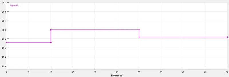
Fig 8: Signal Builder Block
- As per given conditions, the temperature and time are configured using a signal builder block.
- The conditions are, For 0-10s the temperature value is 293 K, For 10-30s the temperature value is 300 K and for 30-50s the temperature value is 296 K.
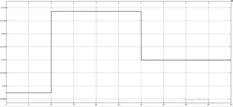
Fig 9: Input Waveform to the Switch
- A voltage sensor is used across the resistor, to measure the voltage as a threshold value.
- FOR the fan condition that is turn On the fan when the temperature is above 296K, set the threshold value as .01099.
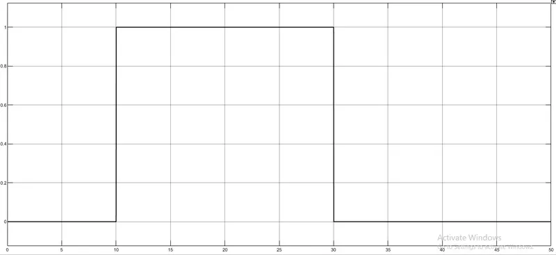
Fig 10: Output Waveform
- To fulfill Fan conditions, add a switch and provide a threshold value, this work as an if-else loop. To give conditions as the right or wrong we add constant blocks.
- If the condition is greater than the threshold value, it will turn On otherwise turn Off the Fan.
#CONCLUSION
Using Thermistor the temperature of the heater is sensed and turned the fan On & Off according to the conditions given:- Temperature source: 20 °C from 0 to 10 seconds, 27 °C from 10 to 30 seconds, 23 °C from 30 to 50 seconds, Fan conditions: ON if the temperature above 25 °C, OFF otherwise.