Week - 4
1) PART 1
# AIM
To Implement control logic of a “washing machine” using Stateflow.
# OBJECTIVE
By using state flow implement the control logic of a “washing machine” as per the given sequence:
- If the power supply is available, the system gets activated.
- If the Water supply is not available, stop the process & indicate through the LED.
- Soaking time should be 200s followed by Washing time of 100s.
- Then rinsing happens for the next 20s & dryer runs for 50s.
- After all the processes have been completed turn on the finished LED.
# WORKING PRINCIPLE WASHING MACHINE
The working principle of a washing machine is centrifugation. Centrifugation is a separation process that uses the action of centrifugal force to promote the accelerated settling of particles in a solid-liquid mixture. The washing machine consists of a centrifuge for this purpose. The centrifuge is a piece of equipment that puts an object in rotation around a fixed axis, applying a force perpendicular to the axis of spin that can be very strong.
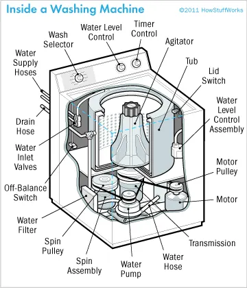
Fig 1: Parts of Washing machine and its working
* WASHING:
Many front-stacking machines have interior electrical warming components to warm the wash water, and to approach bubbling whenever wanted. The pace of the synthetic cleaning activity of the cleanser and other clothing synthetics increments incredibly with temperature, as per the Arrhenius condition. Clothes washers with inner warmers can utilize exceptional cleansers formed to deliver distinctive synthetic fixings at various temperatures, permitting diverse kinds of messes and soils to be cleaned from the garments as the wash water is warmed up by the electrical radiator. Be that as it may, higher-temperature washing utilizes more energy, and numerous textures and elastics are harmed at higher temperatures. Temperatures surpassing 40 °C (104 °F) have the unfortunate impact of inactivating the compounds when utilizing organic detergent. Numerous machines are cold-fill, associated with cold water just, which they warmth to working temperature. Where water can be warmed all the more inexpensively or with less carbon dioxide discharge than by power, the cool fill activity is wasteful. The Front-loaders need to utilize low-sudsing cleansers in light of the fact that the tumbling activity of the drum folds air into the garment's load which can cause over-sudsing and floods. Nonetheless, because of the productive utilization of water and cleanser, the sudsing issue with front-loaders can be constrained by essentially utilizing less cleanser, without reducing cleaning activity.
* RINSING:
Clothes washers play out a few flushes after the fundamental wash to eliminate the greater part of the cleanser. Current clothes washers utilize less water because of ecological concerns; notwithstanding, this has prompted the issue of helpless flushing on many clothes washers on the market, which can be an issue for individuals who are touchy with cleansers. The Allergy UK site recommends re-running the flush cycle or rerunning the whole wash cycle without a cleanser. In light of grievances, many clothes washers permit the client to choose extra flush cycles, to the detriment of higher water utilization and longer process duration. Bosch for instance, in its hypersensitivity wash program, consolidates an extra 3-minute flush cycle with water of in any event 60 degrees Celsius to flush off cleanser deposits and any allergen.
* SPINNING:
Higher twist speeds, alongside bigger tub widths, eliminate more water, prompting quicker drying. Then again, try not to press can be gotten by not utilizing a twisted cycle in the clothes washer. If a warmed garments dryer is utilized after the wash and twist, energy use is decreased if more water has been taken off from garments. Be that as it may, quicker turning can wrinkle garments more. Additionally, mechanical wear on direction increments quickly with rotational speed, diminishing life. Early machines would turn at 300 rpm and, due to the absence of any mechanical suspension, would frequently shake and vibrate.
* SOAKING:
The washer did not immediately wash when added the detergent, but the washer will be intermittent rotation, because there has a soak time, and the washing machine automatically starts washing when the soak time has elapsed.
* DRYER:
A washer-dryer is a washing machine with an inbuilt tumble dryer, so if you need to dry clothes quickly, it’s a good option as it both washes and dries your clothes in the same cycle, so all you need to do is to remove the clothes from the machine and they’re ready to wear.
# CONTROL LOGIC OF WASHING MACHINE
*Case 1: Stateflow model of Washing Machine
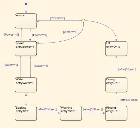
Fig 2: Stateflow of Washing Machine
- This control is done in the state model, each state has names and arguments.
- Each state carries its state name at the left top and their entry values are given with proper syntax.
- It moves from one state to another state only if the conditions are satisfied.
- Here the entry values are 1, it means that during that state the display values are 1, here exit values are not given therefore the display values remain 1 after finishing the state.
- The Power and the supply to the machine are defined by constant values 0 and 1. if the value displayed is 1 then the power and water supply to the machine.
- if the value is 0 and 1 then the machine will not start working and indicates off state by the green lamp.
- if the value is 1 and 0 then the machine will not start working and indicates off state by the green lamp.
- When the power and water both are 1, then the socking process starts and runs for 200s after that washing is done for 100s.
- Then the rinsing process is done for the 20s, after this process, the drying process is started for 50s and then it goes to Off state.
- When each state happens, it is indicated by a green lamp.
* Conditions
(a) Power Supply = 0 & Water Supply=1, when Power supply is not available then the system will not activate.
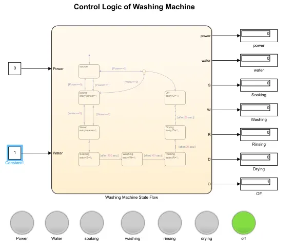
Fig 3: when power supply = 0; the System remains in Off state
- Here power supply is 0, therefore the system does not work and remains in Off State.
- We had modeled the system in such a way that when power or water supply is 0, then the lamp will indicate Off state.
(b) Water Supply = 0 & Power Supply=1, when the water supply is not available then the system will not activate.
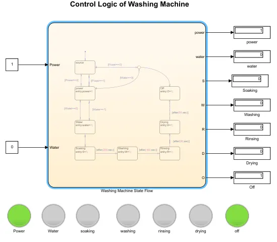
Fig 4: when power supply = 1 but water supply =0; the System remains in Off state
- Here water supply is 0, therefore the system does not work and remains in Off State.
- But the power supply is available therefore power lamp blinks green.
- Here water supply is 0, then conditions are not satisfied for washing machine stages and therefore Off lamp blinks green.
(c) Power Supply and Water Supply =1, When both are 1 then the system starts working.
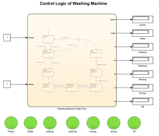
Fig 5: when power supply & water supply =1; the System starts working
- Here both power and water supply are 1, therefore the conditions are satisfied for each stage.
- The machine starts working and for each state lamp indicates green and the output displays 1.
*Case 2: Stateflow model of Washing Machine
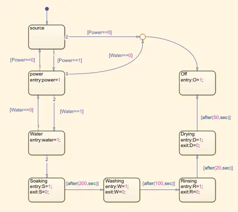
Fig 6: Stateflow of Washing Machine
- This control is done in state model, each state has names and arguments.
- Here the entry values are 1, which means that during that state the display values are 1.
- Here exit values are given that is exit values are 0 therefore the display values change to 0 after the state is finished.
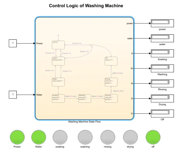
Fig 7: when power supply & water supply =1; the System starts working
- Here during each state the lamp indicates green, but after completing the state the exit value is 0 therefore the lamp does not blink green color after completion of a stage.
# CONCLUSION
Implemented control logic of a “washing machine” using Stateflow as per given sequence:
- If the power supply is available, the system gets activated
- If the Water supply is not available, stop the process & indicate through LED
- Soaking time should be 200s followed by Washing time of 100s.
- Then rinsing happens for the next 20s & dryer runs for 50s
2) PART 2
# AIM
To make a Simulink chart for the “Gear shift” logic.
# OBJECTIVE
Implement Simulink chart for the “Gear shift” logic as per the below conditions:
Speed Range(kmph) Gear
0 to 15 1
16 to 25 2
26 to 40 3
41 to 60 4
Above 61 5
and to give speed input while the simulation is running & display the gear number.
# WORKING PRINCIPLE OF GEAR SHIFTING MECHANISM
In a manual transmission for a back tire drive vehicle, the stuff train is built upon three shafts. Information shaft stretches out from the front of the transmission. An outer parallel-splined area draws in with inner splines on the grip-driven plate. Primary drive gear is a vital piece of the shaft. It networks continually with a mating gear on a counter shaft which has various cog wheels shaped on it. These pinion wheels network with mating gears on the principle shaft, or yield. These primary shaft gears are upheld on orientation on shaft. They can pivot without turning the yield. Every fundamental shaft gear has an outer toothed segment on one side. The teeth face an inside toothed commitment sleeve situated on a focal centre point, which itself splined to the primary shaft. The commitment sleeve can slide one or the other way to draw in the outside teeth on the suitable stuff.
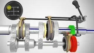
Fig 8: Gear Mechanism
This bolts the stuff through the sleeve and centre, to the principle shaft. The commitment sleeve can slide one or the other way to connect with the outer teeth on the proper stuff. This bolts the stuff through the sleeve and centre , to the principle shaft. Before the commitment of the segments happens, a synchromesh gadget between the sleeve and stuff synchronizes them. Cogwheels continually in the network, have their teeth cut on a helix, at a point to the stuff place line. This decreases gear clamour and circulates load all the more uniformly, as a few teeth are in touch at any one time. Teeth on the opposite idler are regularly straight cut or prod gears, slice corresponding to the stuff place line.The point when the opposite is chosen, interfaces the converse idler with mating gears on the countershaft and principle shaft.
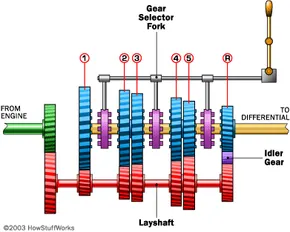
Fig 9: Transmission Mechanism
The opposite idler turns on a plain shaft fixed in the packaging. It moves the drive from one shaft to the next and switches the bearing of the turn of the primary shaft. To effect a gear change, selecting first gear, for example, the driver depresses the clutch, disengaging the input shaft. Using the shift lever, the driver selects the first gear, and the linkage moves the shift junction to connect the 1st-2nd locking collar with the 1st gear, locking it to the output shaft.
# SIMULINK MODEL
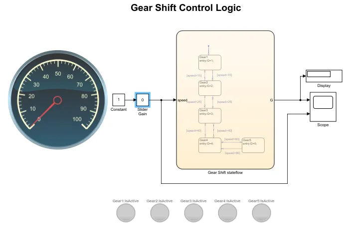
Fig 10: Simulink Model of Gear Shift Control Logic
* Blocks Used for Simulation
- Constant Block: The Constant block generates real or complex constant valued signal. Use this block to provide a constant signal input.
- Slider Block: The Slider block tunes the value of the connected block parameter during simulation. For example, you can connect the Slider block to a Gain block in your model and adjust its value during simulation. Can modify the range of the Slider block's scale to fit your data.
- Stateflow: Stateflow provides a graphical language that includes state transition diagrams, flow charts, state transition tables and truth tables. You can use Stateflow to describe how MATLAB algorithms and Simulink models react to input signals, events and time-based conditions.
- Scope: Display data after simulation, Scope data is saved during a simulation. If it is closed at the start of a simulation, when you open the scope after a simulation, the scope displays simulation results for attached input signals.
- Lamp: Used for Indication. Here it is used for the indication of each gear.
- Display: They are used to show the output values, here used to display gear numbers.
- Circular gauge: Used to show the Speed value.
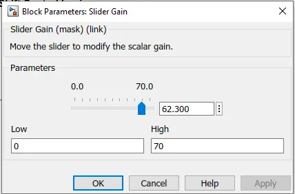
Fig 11: Slider Gain
# Stateflow of Gear Shifting logic
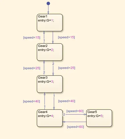
Fig 12: Stateflow of Gear Shifting logic
- At the beginning the slider will be in zero position, there will be no indication in any sensor.
- Spee is varied through slider gain and from there to the control logic system.
- Based on the speed input the gear will be shifted accordingly. Each state represents each gear system.
- if the state satisfies particular conditions the entry value displays as output and Lamp blinks.
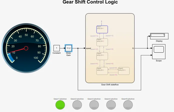
- When the speed is between 0-15 kmph the 1st gear will be executed.
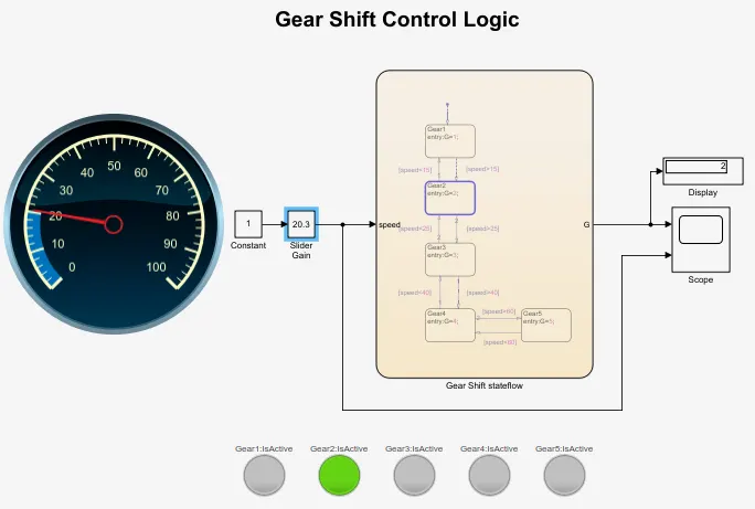
- When the speed is between 16-25 kmph the 2nd gear will be executed.
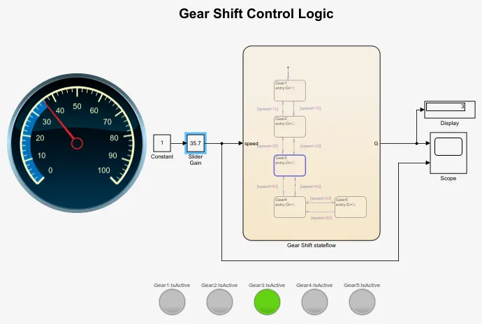
- When the speed is between 25-40 kmph the 3rd gear will be executed.
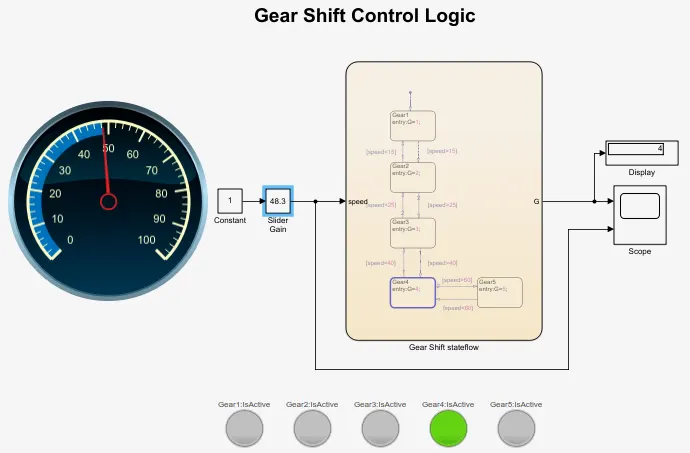
- When the speed is between 41-60 kmph the 4th gear will be executed.
- When the speed is between 60 above kmph the 5th gear will be executed.
# SIMULINK RESULTS
* 1st Gear (0-15kmph)
* 2nd Gear (16-25kmph)
* 3rd Gear (26-40kmph)
* 4th Gear (41-60kmph)
* 5th Gear (61 above kmph)
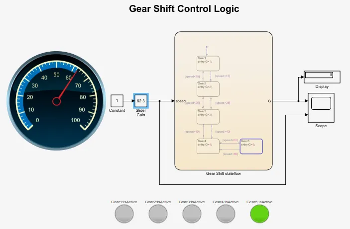
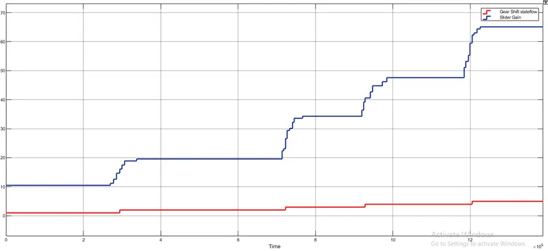
Fig 13: Simulation of Gear shift stateflow and Speed
- From the graph it's clear that gear shiftings are done by the given speed conditions.
- when the speed ranges from 0 to 15kmph, it is in First gear.
- when the speed ranges from 16 to 25kmph, it is in Second gear.
- when the speed ranges from 26 to 40kmph, it is in Third gear.
- when the speed ranges from 41 to 60kmph, it is in Fourth gear.
- when the speed ranges from 61 to above, it is in Fifth gear.
# CONCLUSION
Implemented Simulink chart for the “Gear shift” logic as per the given conditions and Analysed the graph between speed from solver gain and the gear shifting.