Week 9 Challenge
Complete the energy management strategy model with battery, UC and fuel cell for the positive power and distribute the power demand among these components. Set simulation stop time to 598 sec.
The output of the model should be the power request from UC, fuel cell and battery.
Let us assume some conditions for the UC,Battery and FC
| Power demand | Conditions | Source |
| 0-9999 |
if UC-SoC > 35% If UC-SoC < 35% |
UC FC |
| 10000 - 29999 |
if Battery-SoC > 35% if Battery-SoC < 35% |
Battery FC |
| 23000 - 54999 | No condition | FC |
| 55000 and above |
if UC-SoC > 35% if UC-SoC < 35% |
UC FC |
According to therse conditions the Energy Management Stratagey is designed.
Simulation:
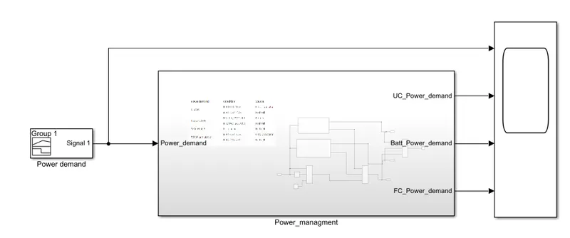
Power demand:
In practical cases the power demand is given by the driver block and powertrain block designed by using the equ. but heare there no such blocks are there so we need to creat the replica of that demand. It is designed by using the Signal block
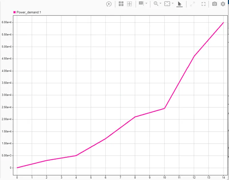
Note that the simulation is done only for the Positive power demand because for negitive power demand the Regeneration will take place in that case the SoC of UC and Battery will change it will be complicated to desigen in tha same model. If the total vehicle model is done it will change automatically because than we will supply the SoC of Battery and UC from the Battery and UC model so this disadvantge will be elimated.
Mode-1: Ultra Capacitor Mode
Step - 1:
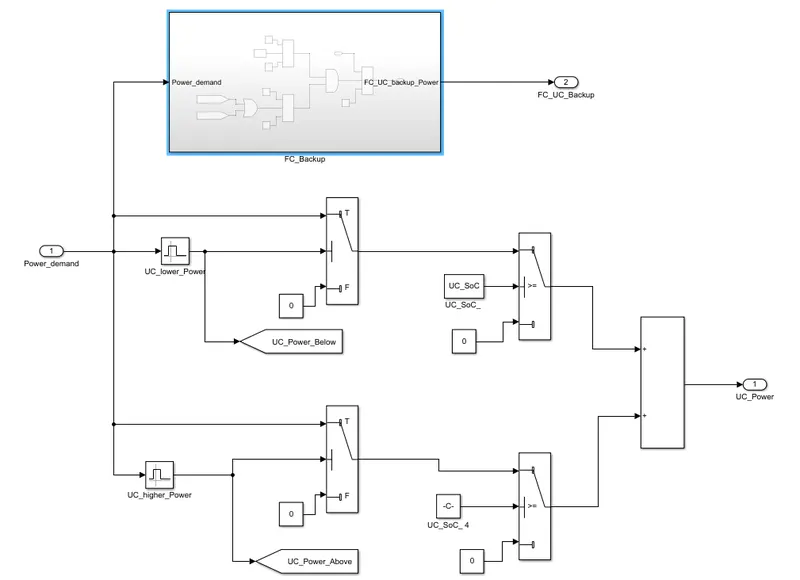
When the power is between the 0 and 9999 and UC_SoC is > 35%
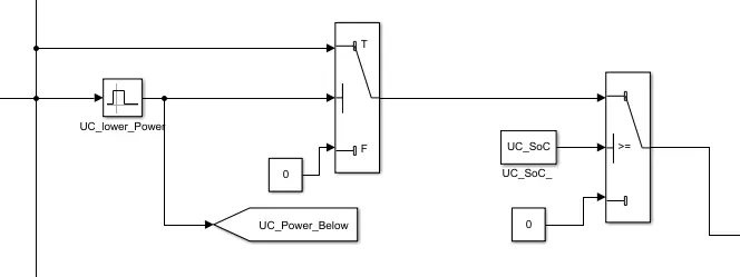
UC_lower_power
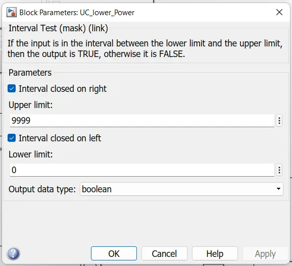
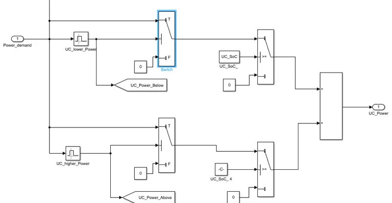
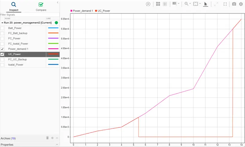
It is designed in such a way that when the both the conditions i.e, Power and SoC conditions are true, it will use the UC power in output otherwise it will give the 0 as output.
Step - 2:
When the power is between the 55000 and above and UC_SoC is > 35%
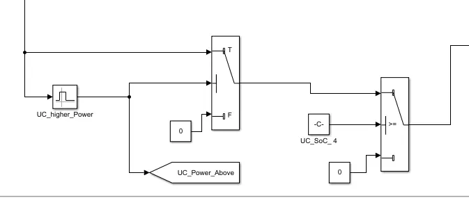
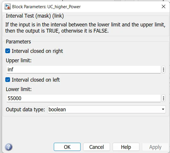
It is designed in such a way that when the both the conditions i.e, Power and SoC conditions are true, it will show the UC power in output otherwise it will give the 0 as output.
Step-3:
Both the step-1 and step-2 should be add to get sresultant UC output. Both the conditions never going to be true at a time so Adding will not effect the output.
Step-4:
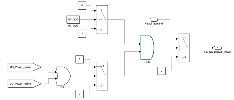
FC_backup calcultion: There is a condition that the power range is in betwee 0 - 9999 or 55000 and above but the UC_SoC i< 35%. In that case we need to use the FC power even though it is in efficient. For that condition the logic is designed as shown below
Mode-2: Battery Mode
Step-5:
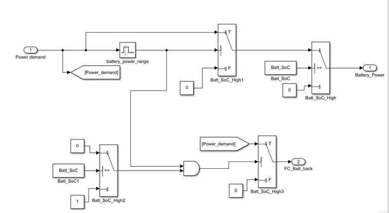
When the power is between the 10000 and 22999 and Battery_SoC is > 35%
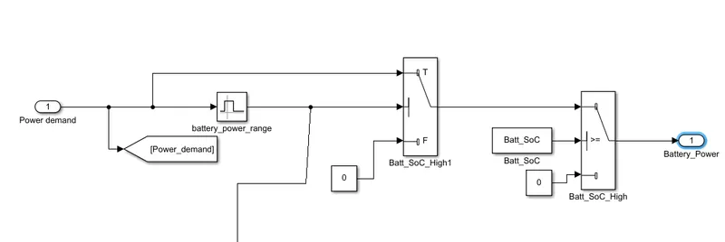
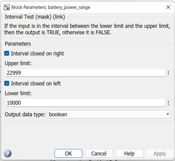
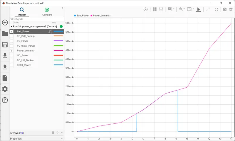
It is designed in such a way that when the both the conditions i.e, Power and SoC conditions are true, it will use the Battery power in output otherwise it will give the 0 as output.
Step-6:
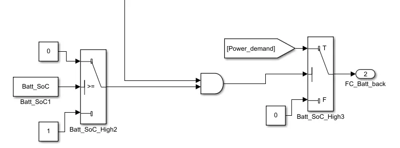
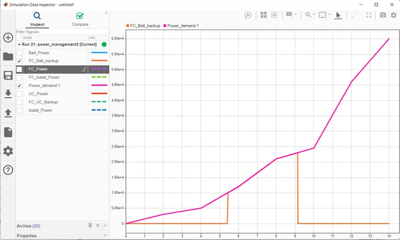
When the condition power is in battery range but the battery SoC is < 35% in that case we need use the FC power even thoug it is in efficient. For that we need FC backup calculation in battery
Mode-3: FC mode
Step - 7:
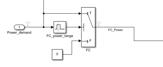
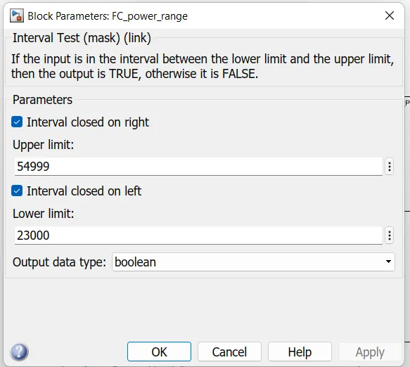
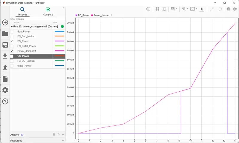
Whe the power is in between 23000 to 54999 and not worring about the any SoC conditions we need to use the FC power for the output. Its design is shown below
Step-8:
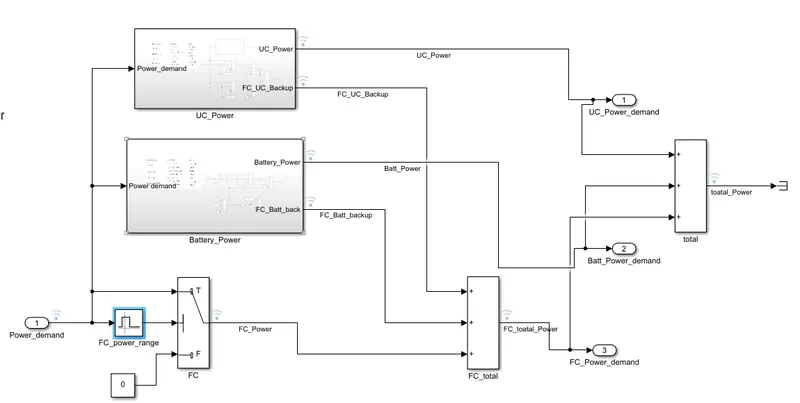
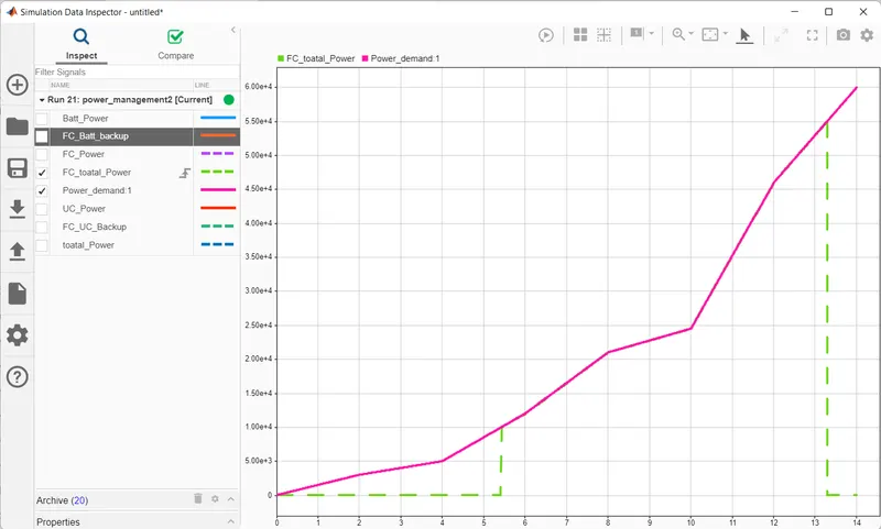
For the FC mode we need to add the step-7 , 6 and 4 to get resultant FC power useage. In practical never all the 3 conditions are not going to be true so by adding them will not effect the output. And adding all the Energy sources we can see the resultant output which will match the power demand.
Results:
To test all the conditions we need to try all the contions which will result in 4 conditions based on the UC and battery SoC and the FC has no conditions it is going to act all the time when the condition is met.
The conditions are
| UC_SoC | Battery SoC | |
| Case-1 | > 35% (use UC) | >35% (use Battery) |
| Case-2 | >35% (use UC) | <35% (use FC) |
| Case-3 | <35% (use FC) | >35% (use Battery) |
| Case-4 | <35% (use FC) | <35% (use FC) |
Case - 1
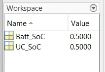
UC_SoC = 0.5
Battery_SoC = 0.5
load the .mat file of case_1 in work space
UC_power sharing:
Battery Power sharing:
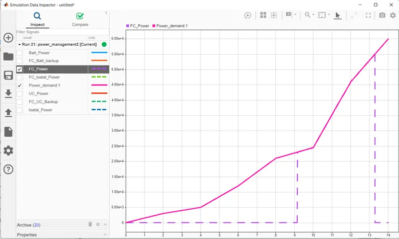
FC power sharing:
Battery and UC back up power by FC is zero because the SoC of both the UC and Battery are above its min value i.e., < 35% which is 50%
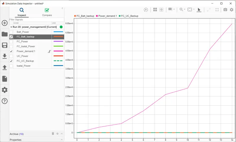
Resultant total output power:
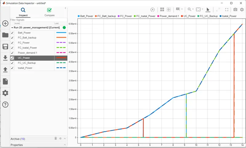
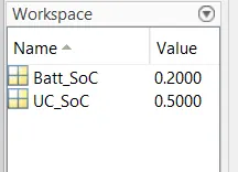
Case-2:
UC_SoC = 0.5
Battery Soc = 0.2
load the .mat file of case_2 in work space
UC power sharig:
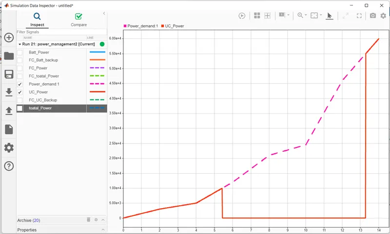
Battery power sharing: is shows zero as the soc < 35% which is 20%
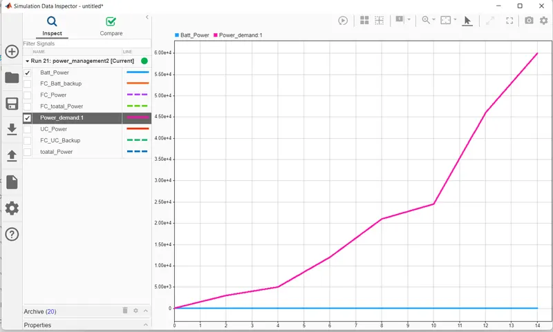
FC power sharing:
Battery backup power by FC
Toatl FC Power:
Like this all the cases output results are uploaded, You can chech that for the different cases.
Conclusion:
We can observe that the Energy management is working accordng to the conditions we assumed.