Week-6 Challenge: EV Drivetrain
Que -1)
Which types of power converter circuits are employed in electric and hybrid electric vehicle?
There are mainly 4 types converters. They are
- Rectifier (AC to DC), converts AC supply to DC supply
- Inverter (DC to AC), Converts DC supply to AC supply
- Regulator(AC to AC), Converts fixed AC to Variable AC i.e., changing the magnitude
- Chopper(DC to DC), Converts fixed DC to variable DC i.e., changing the magnitude
Depending upon their application they are choosen.
- To charge the batter from outside AC to DC converter i.e., Rectifier is used, where it converts the AC supply to DC supply
- To give supply to motor if vehicle use AC motor DC to AC converter i.e., Inverter is used, where it converts the DC supply to AC supply
- To control the vehicle Speed if it uses AC motor the Regulator is used after the Inverter or Chopper is used before the inverter
- To control the vehicle Speed if it uses DC motor the Chopper is used in between the motor and battery.
Like this depending upon their application and use they are choosen.
Que-2)
Given data
Battery voltage (Vs) = 72V
Rated Armature voltage= 72 V
Rated armature current= 400 A
Ra= 0.5Ω,
KΦ= 0.7 Volt second
Chopper Switching frequency= 400 Hz
duty cycle = 70% = 0.7 = d
Wm = speed of the motor in rad/sec
Wv =Speed of the vehicle in rad/sec
The vehicle speed-torque characteristics are given by the below equation
Tv = 24.7 + ((0.0051)Wv^2)..........................................................(1)
we know that motor speed-torque characteristics are given by
Tm = ((d*Vs/KΦ)-Wm)*((KΦ)^2)/Ra .................................................(2)
The Steady state speed of the EV is known as the point where the Speed-Torque characteristics of Vehicle meets the motor Speed-Torque characteristics
At that point the speed and torque values of both vehicle and more are same.
Tv = Tm and Wv = Wm
To find the speed let the Torque of both Vehicle and motor are equal i.e., equating the equ 1 and 2
Tv = Tm and Wv = Wm = W
`24.7 + ((0.0051)Wv^2) =((d*Vs)/(KΦ)-Wm)*((KΦ)^2)/(Ra)`
`24.7 + ((0.0051)W^2) = ((0.7*(72/0.7)-W)*((0.7^2)/0.5)`
`24.7 + ((0.0051)W^2) = (72-W)*0.98`
`24.7 + ((0.0051)W^2) = 70.56-0.98W`
`0.0051W^2 = 45.86-0.98W`
`0.0051W^2+0.98W-45.86 = 0`
It is a Quadratic equation and the roots of this equation are
W1 = -231.0718 and W2 = 38.9150
As the Speed will not br negitive. So the speed will be 38.9150 rad/sec
The Steady State Speed of the vehicle is 38.9150 rad/sec
Que-3):
Sub. the Steady state Speed in equ(1) or equ (2) to get Steady State Torque
Equ(1) sub Wv = 38.9150 rad/sec
Tv = 24.7 + ((0.0051)Wv^2)
`Tv = 24.7 + ((0.0051)38.91^2`
Tv = 32.5748 Nm
Equ(2) sub Wm = 38.9150 rad/sec
`Tm =((0.7*(72/0.7)-W)*((0.7^2)/0.5)`
Tm = 32.4233 Nm
It shows Tv =Tm
Conclusion
EV steady state speed if duty cycle is 70% = 38.915 rad/sec
Que-3)
*Case-1)
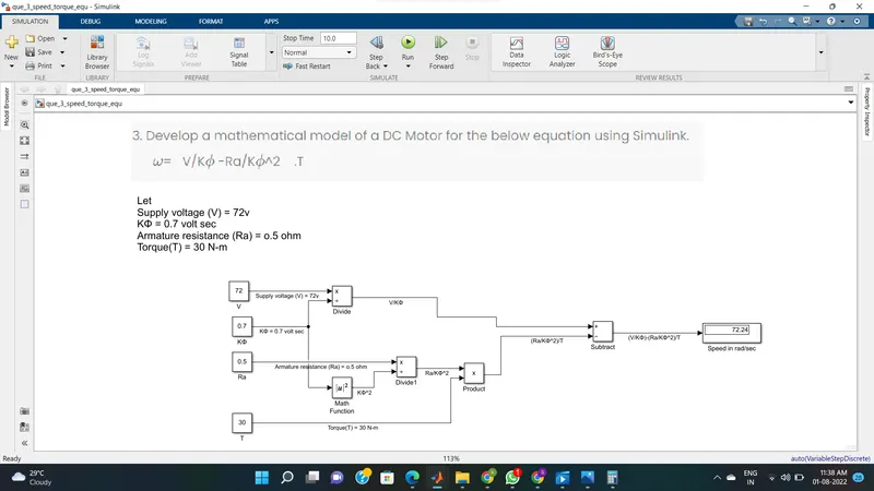
Develop a mathematical model of a DC Motor for the below equation using Simulink.
ω= V/Kϕ -Ra/Kϕ^2 .T
Let input data be
Supply voltage (V) = 72v
KΦ = 0.7 volt sec
Armature resistance (Ra) = o.5 ohm
Torque(T) = 30 N-m
Simulation model:
To design this above inputs are taken as Constant Blocks and using some product blocks,division block the model was designed acoording to equation. The output was shown by the Display Block.
Note that the output was in rad/sec
Model file is Uploaded with the name "que_3_speed_torque_equ.slx"
Result :
The speed is 72.24 rad/sec
*Case-2)
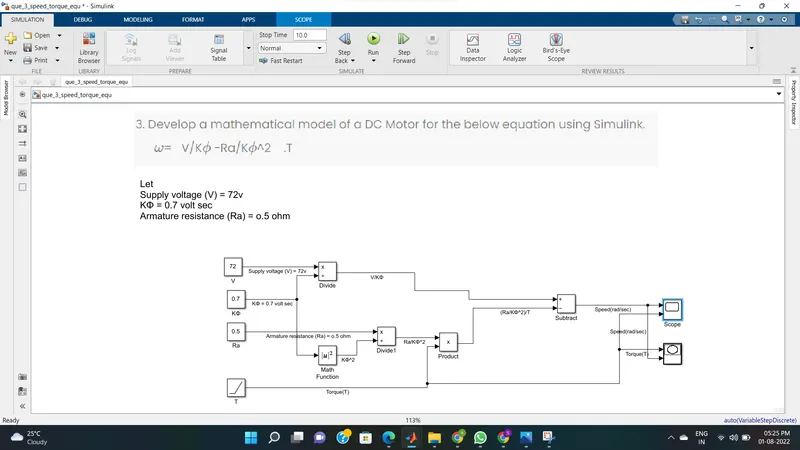
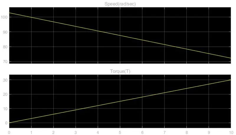
If we want to check how the speed chages with chagen in Torque, the Torque block is takes as ramp. It indicates that gradually increasing in torque. According to it the speed also changes. The peak value of Torque is taken as 30 Nm
Model file is Uploaded with the name "que_3_speed_torque_equ2.slx"
Change in Speed and Torque
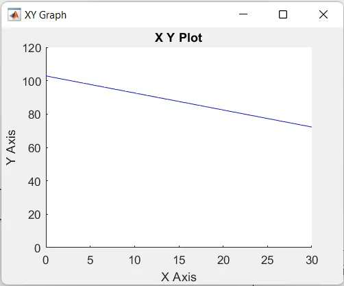
Speed - Torque characteristics
X-axis = Torque
Y-axis = Speed
Que-4)
The author Wally Rippel given the details about the Type of motors suites for EV. Mainly he discussed about the 2 types of motors they are Brushless DC motor and Induction motor.
His point says that both motors has their own advantages and disadvantages over eachother. Sometimes the disdavntages are overcomed by R&D by modifing the design and control. Even though they are updated the disavantages are not fully overcomed.
Accorting to him the type of motor was choosen such that the it has to satisfy the customer requirment.Like if it comes cost point of view the Induction is more sutied than BLDC, if controlling point the BLDC motor suited more than the Induction Motor ect., like this numberof points are taken into concideration and Motor was choosen.
He says that DC brushless drives will likely continue to dominate in the hybrid and coming plug-in hybrid markets, and that induction drives will likely maintain dominance for the high-performance pure electrics. The question is what will happen as hybrids become more electrically intensive and as their performance levels increase?
Brushless DC motor
With brushless machines, the rotor includes two or more permanent magnets that generate a DC magnetic field (as seen from the vantage point of the rotor). In turn, this magnetic field enters the stator core (a core made up of thin, stacked laminations) and interacts with currents flowing within the windings to produce a torque interaction between the rotor and stator. As the rotor rotates, it is necessary that the magnitude and polarity of the stator currents be continuously varied – and in just the right way - such that the torque remains constant and the conversion of electrical to mechanical energy is optimally efficient. The device that provides this current control is called an inverter. Without it, brushless motors are useless motors.
Induction Motor:
the induction rotor has no magnets – just stacked steel laminations with buried peripheral conductors that form a “shorted structure.” Currents flowing in the stator windings produce a rotating magnetic field that enters the rotor. In turn, the frequency of this magnetic field as “seen” by the rotor is equal to the difference between the applied electrical frequency and the rotational “frequency” of the rotor itself. Accordingly, an induced voltage exists across the shorted structure that is proportionate to this speed difference between the rotor and electrical frequency. In response to this voltage, currents are produced within the rotor conductors that are approximately proportionate to the voltage, hence the speed difference. Finally, these currents interact with the original magnetic field to produce forces – a component of which is the desired rotor torque.
Here are some of the points comparing the both BLDC and Induction motors
- The strength of the magnetic field produced by the permanent magnets would be adjustable. When maximum torque is required, especially at low speeds, the magnetic field strength (B) should be maximum – so that inverter and motor currents are maintained at their lowest possible values. This minimizes the I² R (current² resistance) losses and thereby optimizes efficiency. Likewise, when torque levels are low, the B field should be reduced such that eddy and hysteresis losses due to B are also reduced. Ideally, B should be adjusted such that the sum of the eddy, hysteresis, and I² losses is minimized. Unfortunately, there is no easy way of changing B with permanent magnets.
- Induction machines have no magnets and B fields are “adjustable,” since B is proportionate to V/f (voltage to frequency). This means that at light loads the inverter can reduce voltage such that magnetic losses are reduced and efficiency is maximized. Thus, the induction machine when operated with a smart inverter has an advantage over a DC brushless machine – magnetic and conduction losses can be traded such that efficiency is optimized. This advantage becomes increasingly important as performance is increased. With DC brushless, as machine size grows, the magnetic losses increase proportionately and part load efficiency drops. With induction, as machine size grows, losses do not necessarily grow. Thus, induction drives may be the favored approach where high-performance is desired; peak efficiency will be a little less than with DC brushless, but average efficiency may actually be better.
- Permanent magnets are expensive – something like $50 per kilogram. Permanent magnet (PM) rotors are also difficult to handle due to very large forces that come into play when anything ferromagnet gets close to them. This means that induction motors will likely retain a cost advantage over PM machines. Also, due to the field weakening capabilities of induction machines, inverter ratings and costs appear to be lower, especially for high performance drives. Since spinning induction machines produce little or no voltage when de-excited, they are easier to protect.
- Induction machines are more difficult to control. The control laws are more complex and difficult to understand. Achieving stability over the entire torque-speed range and over temperature is more difficult with induction than with DC brushless. This means added development costs, but likely little or no recurring costs.