Project - Speed Control of a Direct Current (DC) motor
DC motor speed controller using PID controller:
The simulation model is diveided into 2 parts
1. The DC motor
2. PID controller
1. DC motor
By taking the given parameters as shown in fig. i.e.,
Jm=0.01; %Moment of Inertia in kg/m^2
Bm=0.1; %Motor Viscous Friction constant N-m-s
Km=0.01; % Back emf constant v/rad/s
Kt=0.01; % Motor Torque cosntant N-m/amp
Ra=1.0; % Resistance of the armature circuits in ohms.
La=0.5; % Inductance of the armature circuits in Henry
the design is made by using the equations
Mathematical Modeling
1. Ia = (Vs - Vb)(1/(La.S + Ra)) where Vs is the supply voltage and Vb is the back emf
2. W = T/(Jm.S + Bm) where tough Tau = T is the torque and W is the speed of the motor
* note that the filed current is kept contastant
Simulation model :
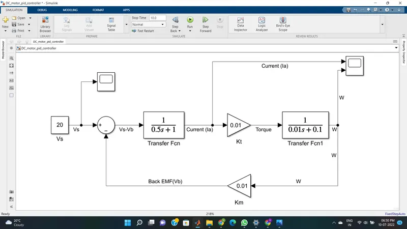
2) PID controller design
The speed of the DC moter can be varied or controlled by controlling the supply voltage (Vs). The PID controller is designed in such a way that it controls the supply voltage(Vs). That is shown in the below equation.
for designing the PID controller we need to take the basic equation of the PID conroller i.e..
u(t) = Kp*e(t) + Ki*int(e(t)dt) + kd*d e(t)/dt
where u(t) = Vs
e(t) = Wref - W i.e referance speed - origial speed
the equation can be modified into
Control law for PID design
Vs = Kp*(Wref - W) + Ki*int((Wref - W)dt) - kd*Ia
simulation :
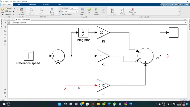
Now by combaining both the models we can control the speed of the motor. that is we can operate the motor at desired speed.
simulation:
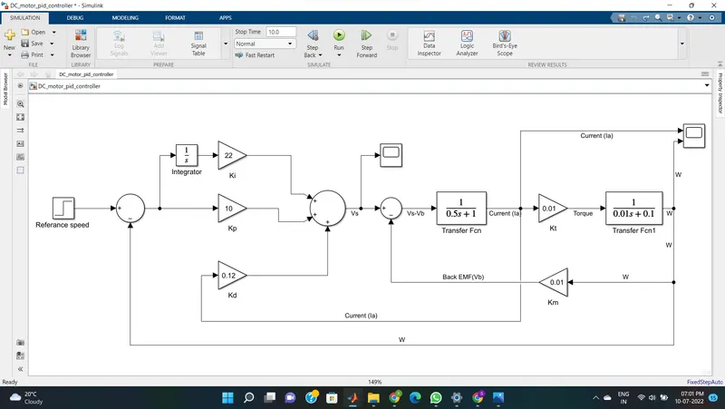
By using the open loop TF of the DC motor we can find the Poles for ploe placement method.
Matrix A and B are found from the state space model of a DC motor i.e.,
d/dt *[teta_dot ; i] = [-Bm/Jm Kt/Jm ; -Km/La -Ra/la]*[teta_dot ; i] + [0 1/La]*Vs
y = [1 ; 0] * [teta_dot ; i] + [0]*Vs
where A = [-Bm/Jm Kt/Jm ; -Km/La -Ra/la]
B = [teta_dot ; i]
* teta_dot = speed of the motor (W)
matrix P is found from the open loop Transfer function of the DC motor denominator i.e poles
equ. => W(S)/Vs(S) = Kt/(Jm*La(S^2) + Jm*Ra+Bm*La(S) + Bm*Ra+Kt*Km)
Code : in script window
%DC Motor Design
Jm=0.01; %Moment of Inertia in kg/m^2
Bm=0.1; %Motor Viscous Friction constant N-m-s
Km=0.01; % Back emf constant v/rad/s
Kt=0.01; % Motor Torque cosntant N-m/amp
Ra=1.0; % Resistance of the armature circuits in ohms.
La=0.5; % Inductance of the armature circuits in Henry
% PD design
%Plant matrices
A=[-Bm/Jm Kt/Jm; -Km/La -Ra/La];
B=[0; 1/La];
%Pole Placement design
P = roots([Jm*La Jm*Ra+Bm*La Bm*Ra+Kt*Km])
K=place(A,B,P);
Kp = K(1)
Kd = K(2)
by using the pole placement method the Kp and Kd are found i.e Kp = -1.4606e-15 nad Kd = 2.2204e-16
but the poles which are found are not accurate i.e the stablity,settling time and steady state error are bad.
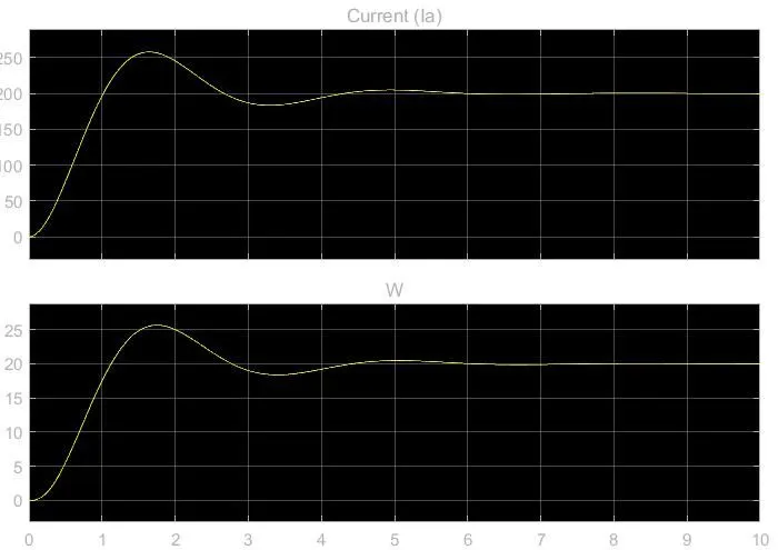
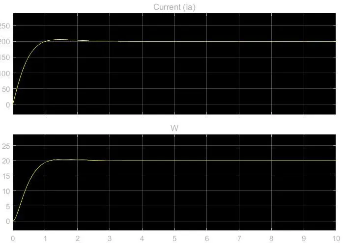
so to get the system to stable , less settiling time and less steady state error are found by changing Kp,Kd,Ki gains i.e.,
Kp = 10
Kd = 0.12
Ki = 22
*these valus are found by trial and error method i.e by changing the values and checking the graph and comparing with old values
here the referace speed Wref = 20 i.e the value of desired speed of DC motor
Conclusion:
The speed of the DC motor is controlled and made to run at desired value. In this case 20.
It is very important that choose the Kp,Kd and Ki values in such a way that system is highly stable.