Week 10 - Challenge 2- Attachment Feature Creation (Dog House)
AIM: - Design of the Dog House for the Door Trim following the design rules.
OBJECTIVE: -
- For the provided CLASS -A surface, create a Tooling axis.
- Using the particular CLASS-A surface, create the CLASS-B and C surfaces of the door trim.
- Create a final surface model and convert it to a solid body on the part design workbench by using the close surface command.
- Create the dog house's side core axis.
- Consider the design criteria while creating a dog home on the B surface.
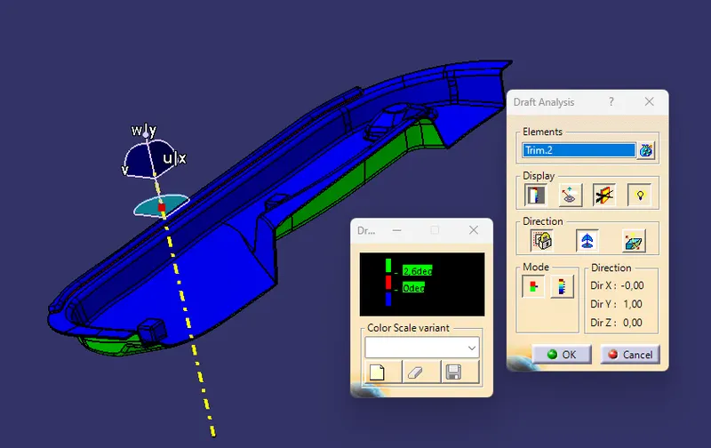
- Draft Analysis of both the Class-A surface and the Final component body.
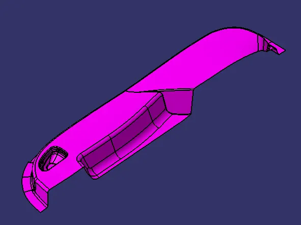
GIVEN CLASS A SURFACE
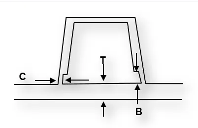
DESIGN RULE TO FOLLOW FOR THE CREATION OF DOG HOUSE
-
Doghouse wall thickness at the intersection of the part wall ( C ) should be 40% or less than the main wall stock ( T ).
-
The height of ( B ) should be between 3.0 – 6.0 mm
CREATION OF TOOLING AXIS
In injection moulding, the tooling axis is initially created by analysing the Class-A surface. Tooling direction is critical for plastic product design since it determines mould separation direction.
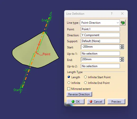
We must first determine the best acceptable tooling direction using the compass to establish the tooling axis. Because most surfaces are cleared in the y direction while doing draft analysis, the y direction is appropriate for constructing the tooling axis. Normally, the tooling axis is generated by bisecting a line, however, in this case, a line normal to the surface is created in the y direction and used as the tooling axis.
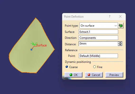
- Extract the CLASS-A surface.
- Create a point on the extracted surface.
- Now, draw a line using the point direction along the y-direction, Tooling Axis.
DRAFT ANALYSIS OF CLASS A SURFACE
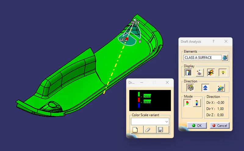
- We do a draft analysis after creating a tooling axis. Before we begin further, we must ensure that the materials are chosen in the view mode.
- We drag the compass from its current location to the tool axis after selecting the feature draught analysis tool. Then secure the compass. After that, choose anywhere on the component to see the outcome.
- We reduce the component's minimum draught to 3°.
- To examine the angle of the component, we may utilise the running point option.
CREATION OF CLASS B SURFACE
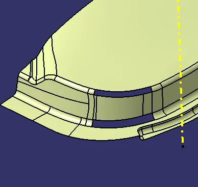
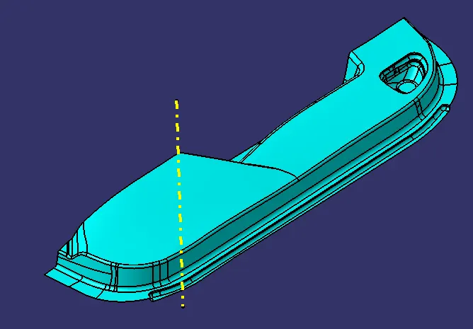
Class-B surface refers to the thickness of a part that is not visible and is located inside the part. In other words, the Class-B surface is one that is thinner than the Class-A surface. This is the surface of a model that comprises engineering characteristics.
- Create an offset surface of CLASS-A approximately 2.5mm inward.
- Examine the offset surface for discontinuity and rework it using extract, multi-extract, and multi sections surfaces.
- Join the surfaces to guarantee that the final CLASS-B surface has no gaps.
CREATION OF CLASS C SURFACE
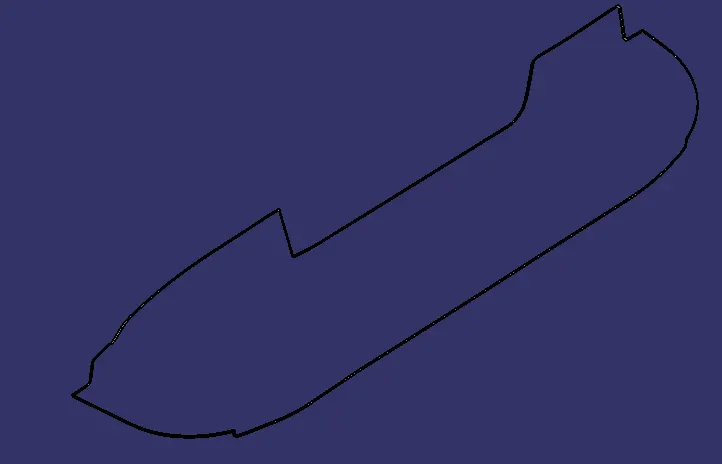
Class-C surfaces are those that connect class-A and class-B surfaces. Class C is frequently specified for interior surfaces that are not easily visible and will be covered by another item when completed.
- Create the sweep with regard to the surface and tooling axis multiple-extracting the CLASS-A boundary.
- Extrapolate and multi-section surface commands can be used to join the sweep surfaces.
- Finally, connect all of the sweep surfaces to assure the CLASS-C surface's continuity.
CREATION OF SOLID BODY
- Join the CLASS-A and CLASS-C surfaces to make the Finals door trim surface.
- Then, extrapolate the B surface slightly outward to ensure that there is no gap when trimming with the linked surface.
- The extrapolated CLASS-B surface is then trimmed with the Join surface (CLASS-A and CLASS-C).

CREATION OG DOG HOUSE
- Create a sketch on a plane of the surface on which we want to build the dog home.
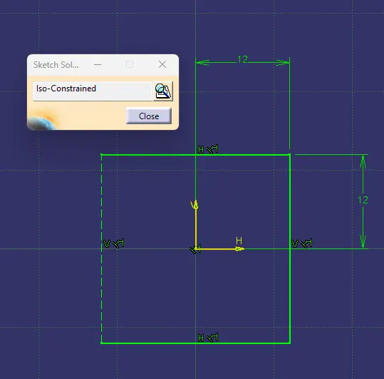
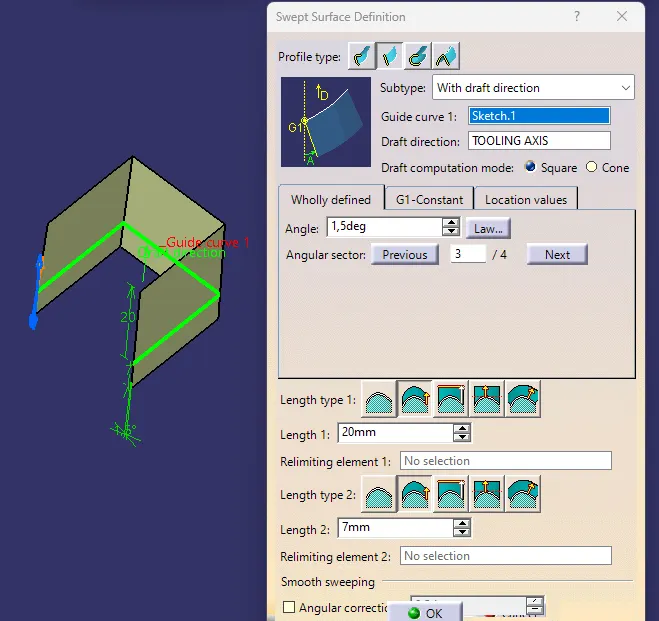
- Create the outer walls of the dog hose using the extrude or sweep method.
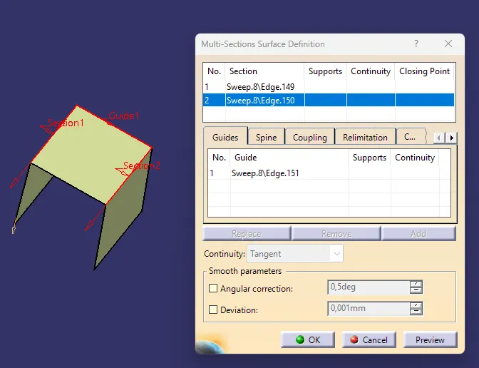
- Now use the multi-section surface command to close off the top wall.
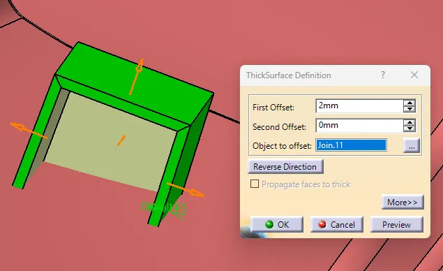
- Create a solid component of the dog home in the part workbench by using the thicken command.
- As the side core axis, apply the draft angle to the inside walls and pull direction.
- The height of (B) should be between 3.0 and 6.0 mm, and we offset the class b surface to 4mm using the design rule.
- The thickness of the doghouse wall at the intersection of the portion wall (C) and the main wall stock (T) should be 40% or less.
- We used the design rule to offset the 1mm from the side wall.
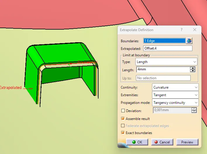
- Finally, we trimmed the surfaces and divided the surface with the portion body. The design principles are followed when building the dog home.
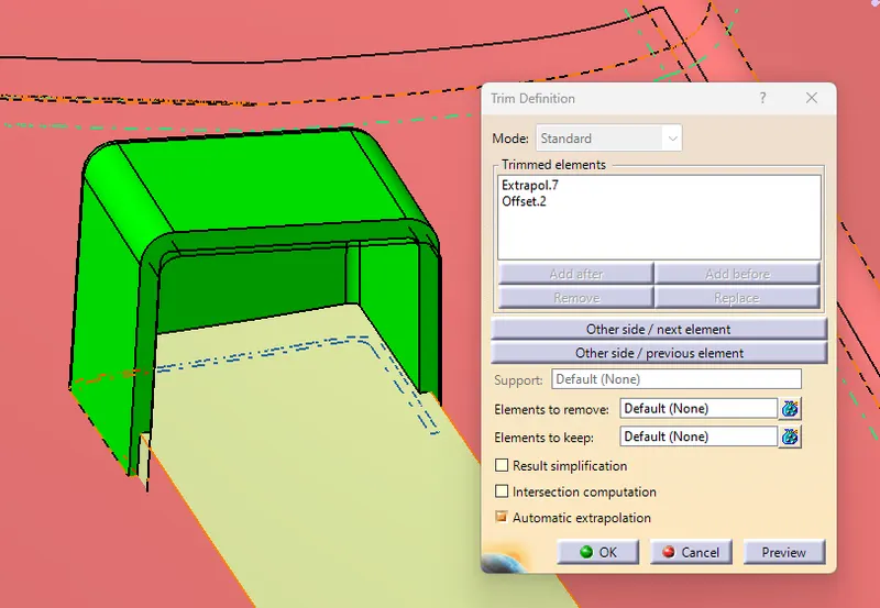
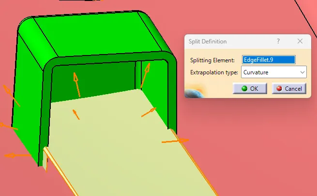
- Finally, the dog house formed.
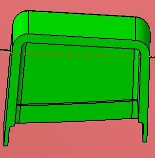
- In the end, union trim with a solid body and follow the same procedure to create another Dog House.
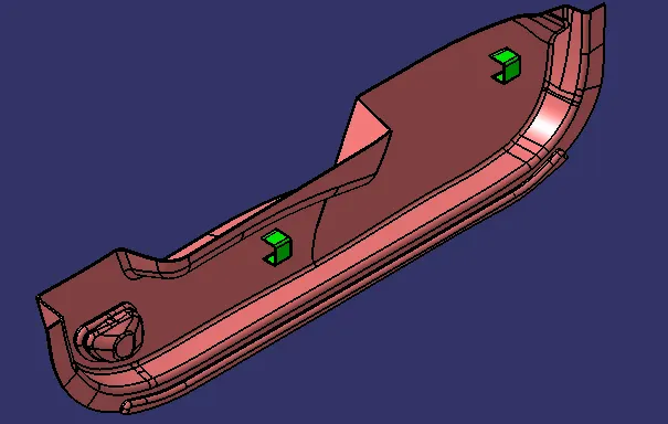
DRAFT ANALYSIS OF THE FINAL BODY
- In the display frame, alter the material mode of the produced part.
- The compass is activated and aligned with the tooling direction.
- The lock command is then used to secure the compass as well as the tooling axis.
- Colour codes are assigned, and a draft angle is used.
- Running point analysis is used to illustrate draft angles that are permitted.
Screenshots of the completed design in various orientations (Isometric, Front, Side, and Top View)
FRONT VIEW
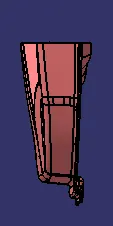
RIGHT HAND SIDE VIEW
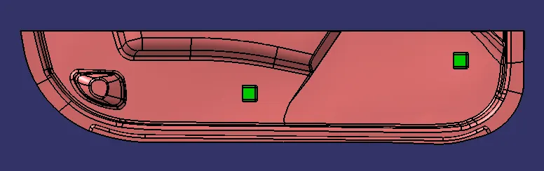
LEFT HAND SIDE VIEW
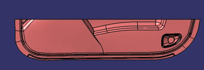
TOP VIEW
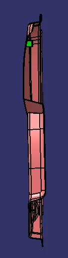
ISOMETRIC VIEW