Week 9 - Challenge 3 - Bumper
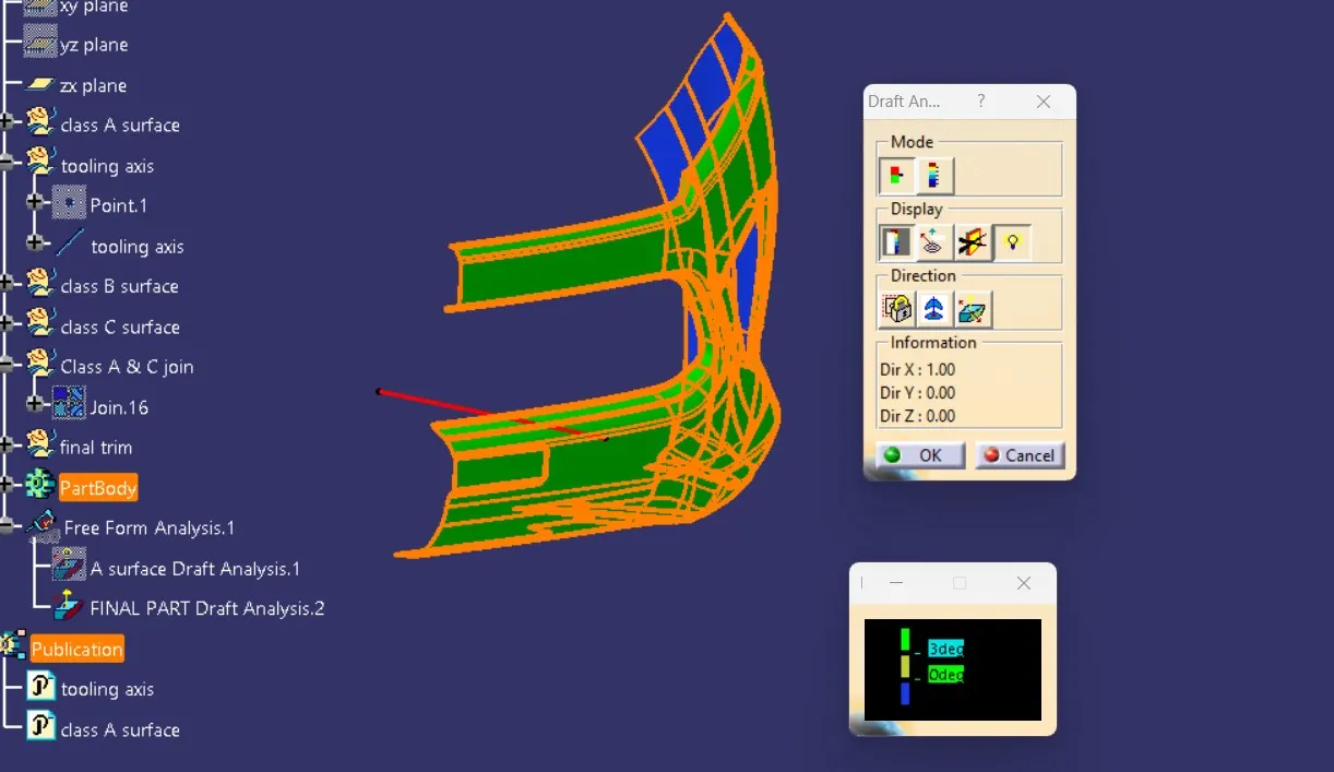
Objective: To design the Bumper Plastic component based on the provided Class-A surface. Start by generating the tooling axis for the given Class-A surface, ensuring it adheres to the required draft angle specifications. Finally, perform a draft analysis on the model.
Assume the component thickness is 3 mm.
GIVEN CLASS A SURFACE :
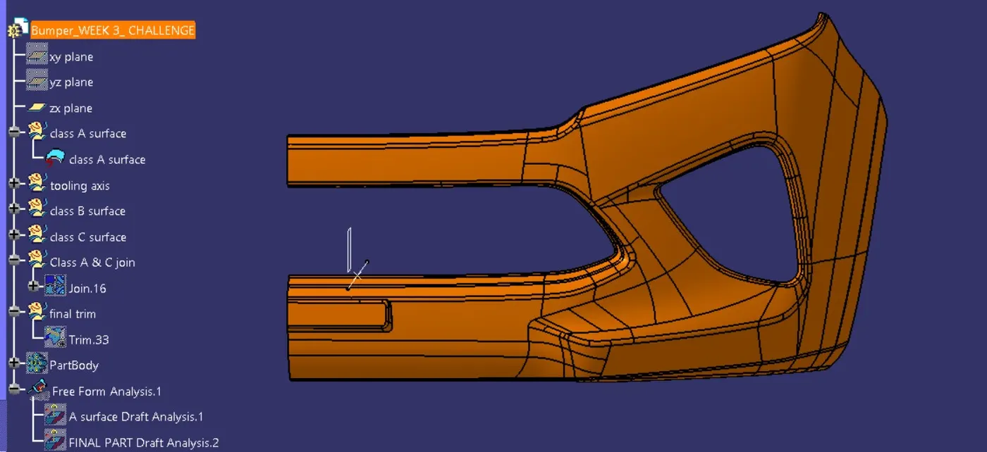
DRAFT ANALYSIS OF GIVEN CLASS A SURFACE -
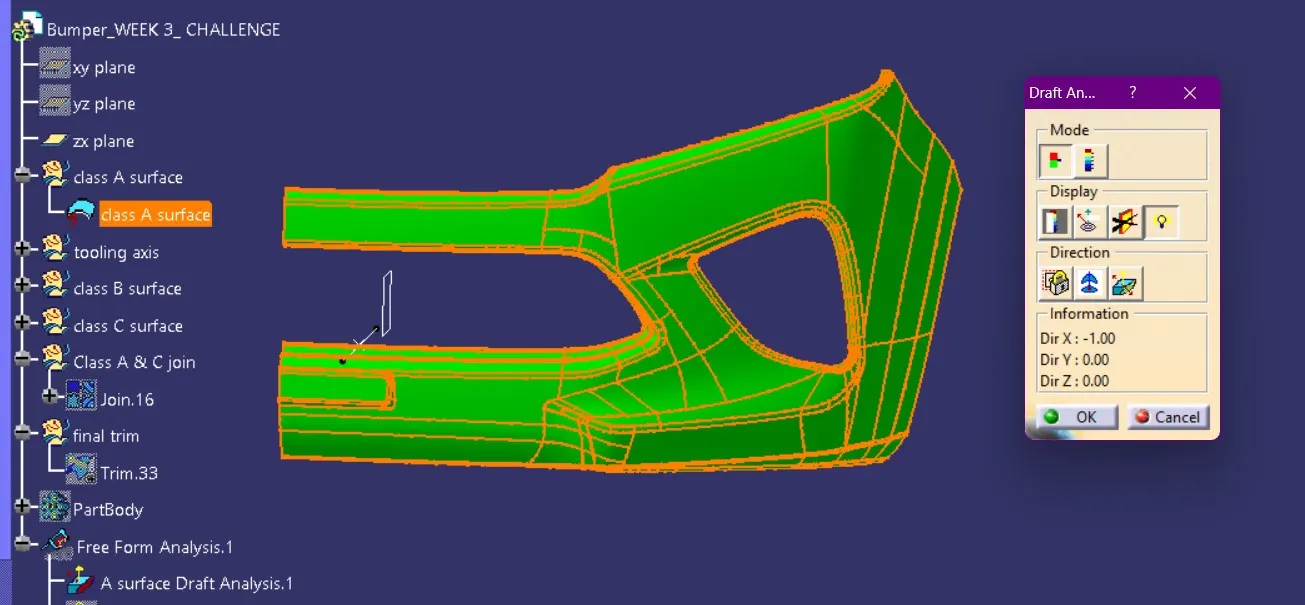
Main Tooling Axis: To create the main tooling axis, identify a flat surface on the Class-A surface. Then, create a reference line on this surface with all dimensions set to 0.
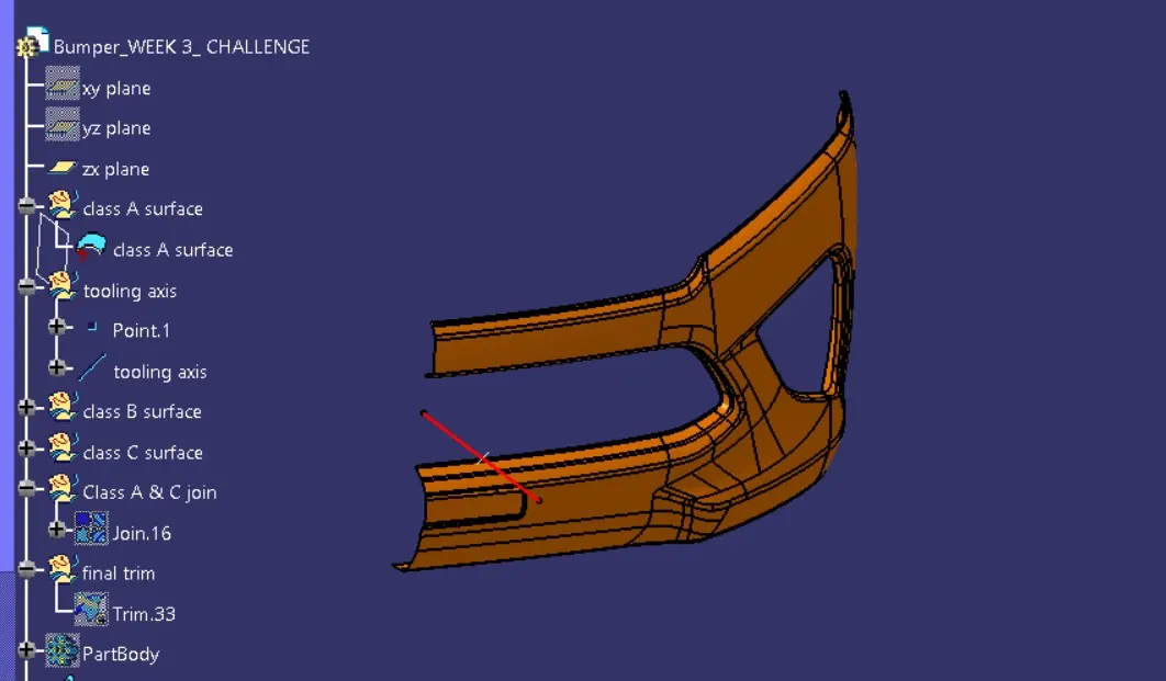
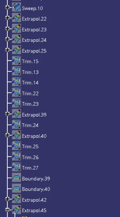
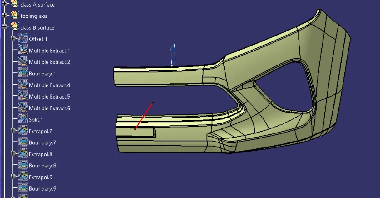
Class B Surface: To create the Class B surface, offset the Class-A surface by 3 mm. Then, close all open patches using extrapolation and trimming functions. The final Class B surface is shown below
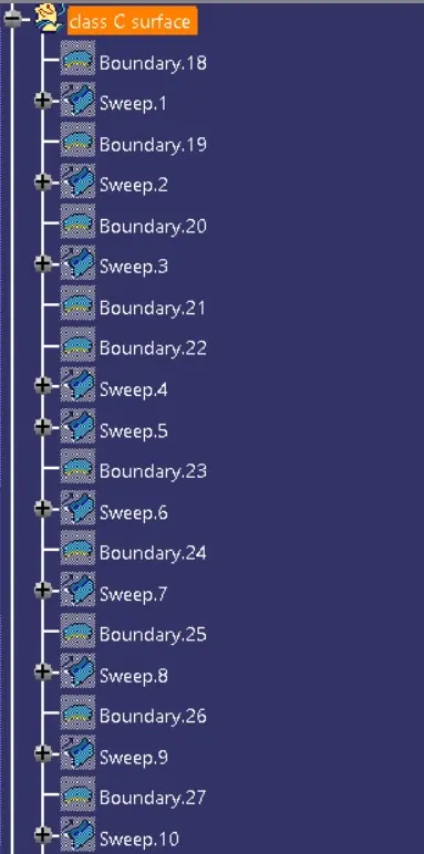
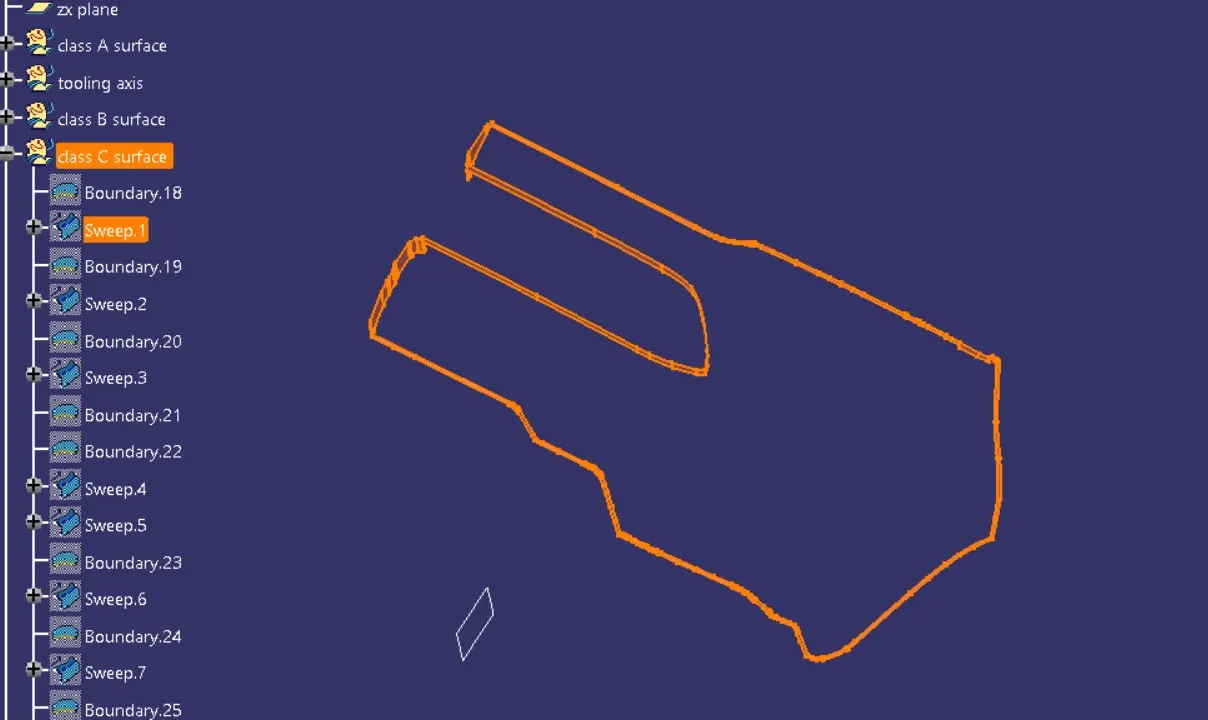
Class C Surface: To create the Class C surface, use the Sweep command, referencing the Class B surface. The length for the sweep should be set to 5 mm.
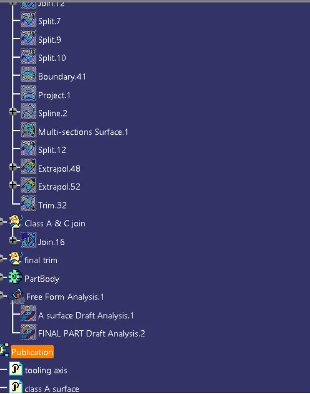
Final Trimmed Surface: To create the final trimmed surface, first join the Class A and Class C surfaces. Then, trim the combined surface using the Class B surface
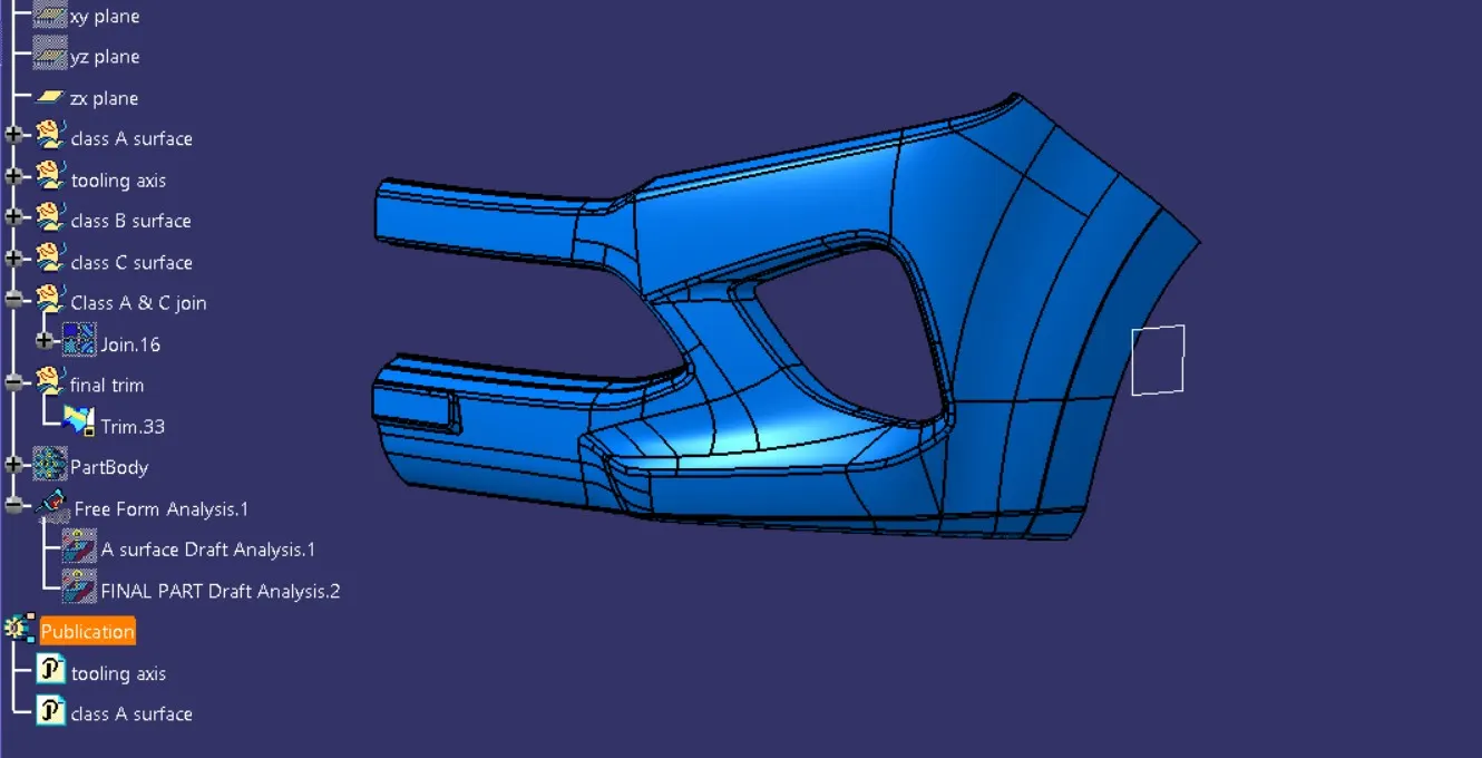
Draft Analysis of Final Trimmed Surface: Perform a draft analysis on the final trimmed surface to ensure that the angles of the surfaces are in compliance with the required draft specifications. This analysis helps to verify that the part is suitable for manufacturing and will properly release from the mold .
FINAL BUMPER PART -
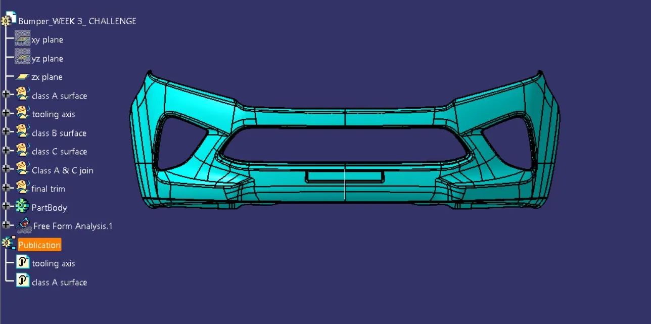
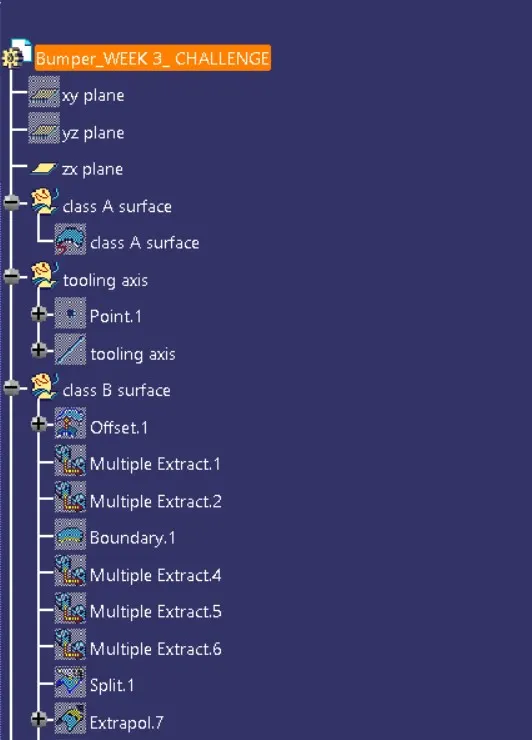
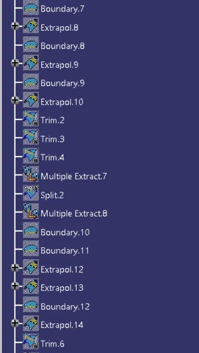
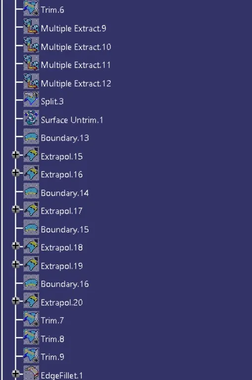
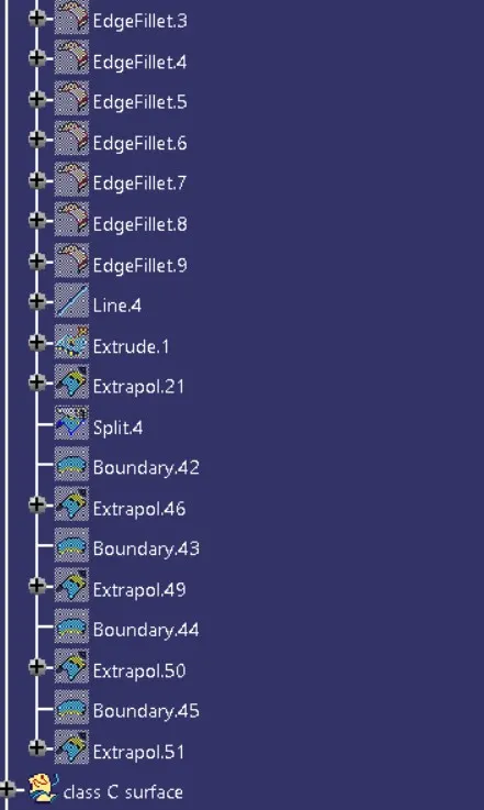
TREE STRUCTURE: