Week 9 - Challenge 3 - Bumper
v W9_CHALLENGE 1
Aim: - To create a Bumper Plastic Component through a given Class A Surface and perform Draft
Analysis on the final plastic component.
Objectives:
- Creation of Tooling Axis.
- Creation of Class B and Class C surface.
- Creating a solid part out of surface modelling.
- Draft Analysis of Class A surface and final plastic component.
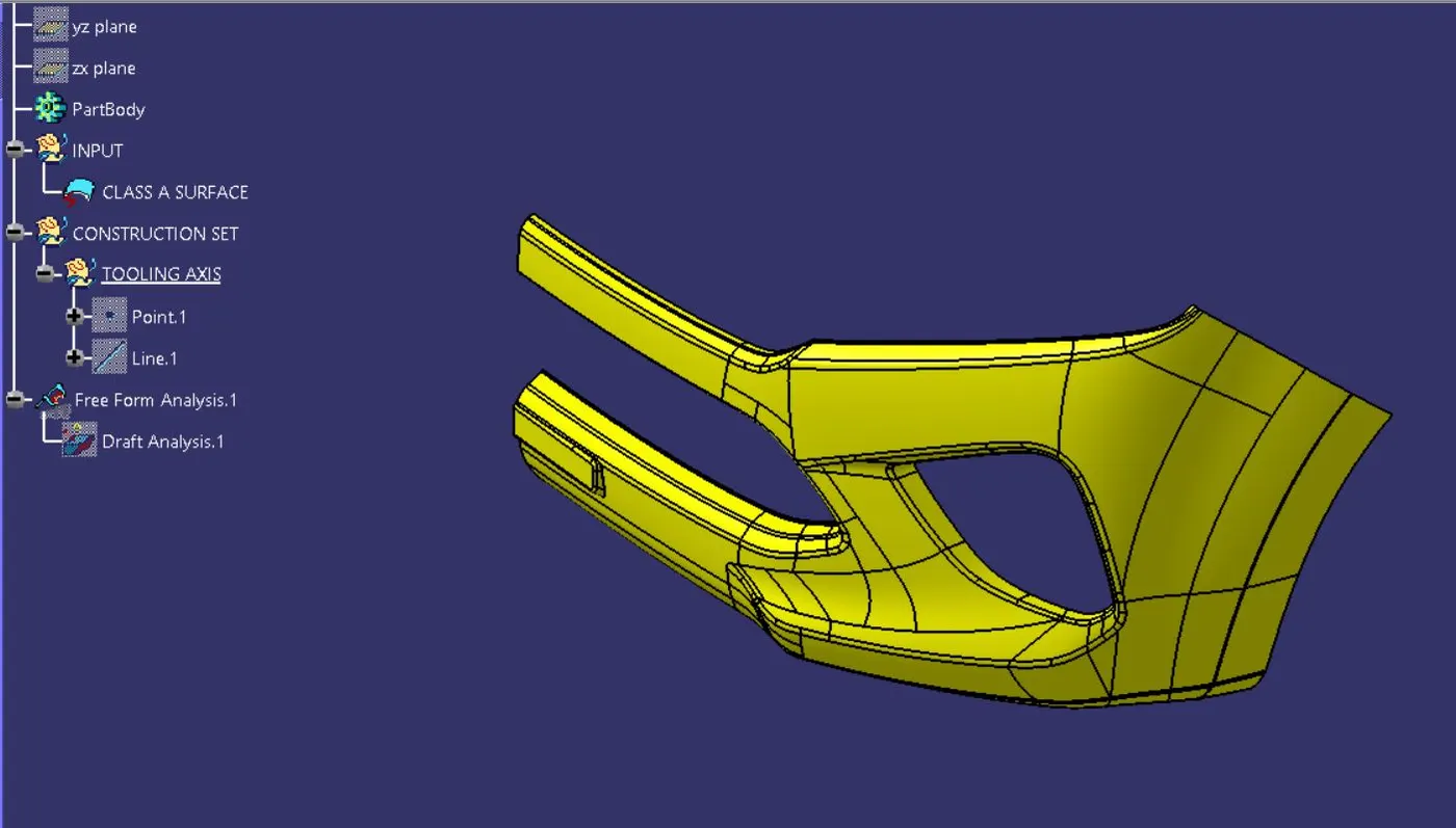
Provided Class A surface for component is shown below:
Identifying Tooling Axis
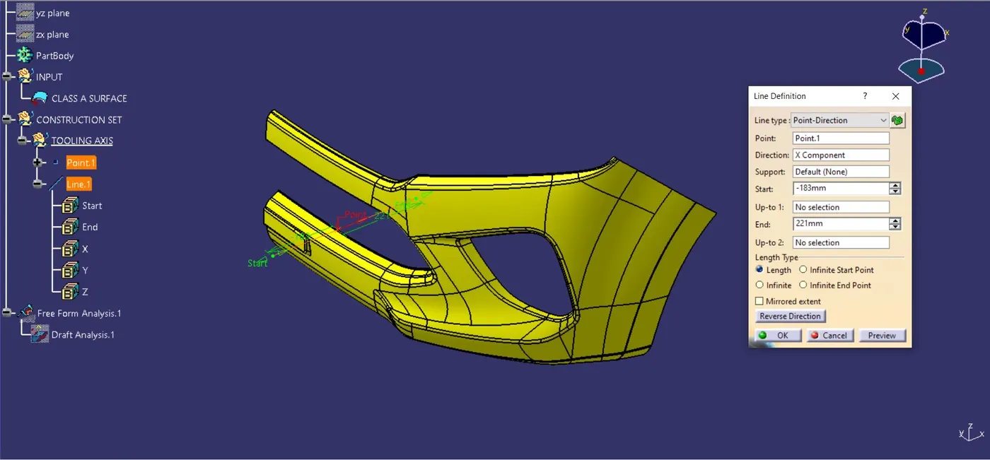
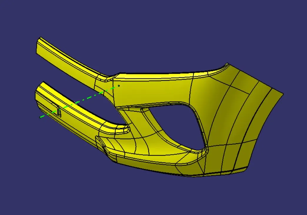
· On inspecting the part, the X-Axis is the best option for tooling the component.
· As shown in image a Middel-point is created on the Edge of the surface and the tooling axis is created using X-Axis & the Point as reference.
Draft Analysis of Class A surface is shown below:
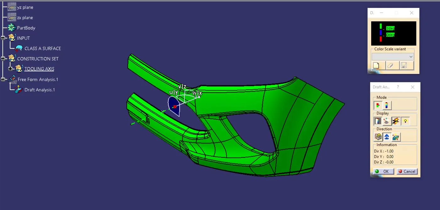
· To manufacture the Tooling component, Draft analysis is done on it.
· Industrial std. is of 3° and as it is seen in the above the draft on provided class A surface is more than the acceptable value.
Creating Surface B
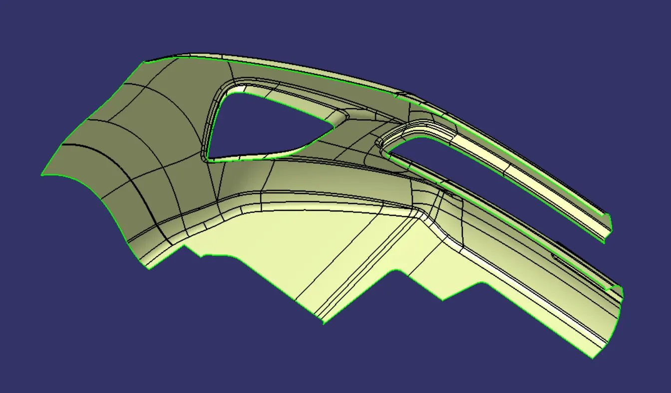
· Using extrapolate and off-set command the surface B is created which is shown in below image of off-set value of 3mm.
Creating Surface C
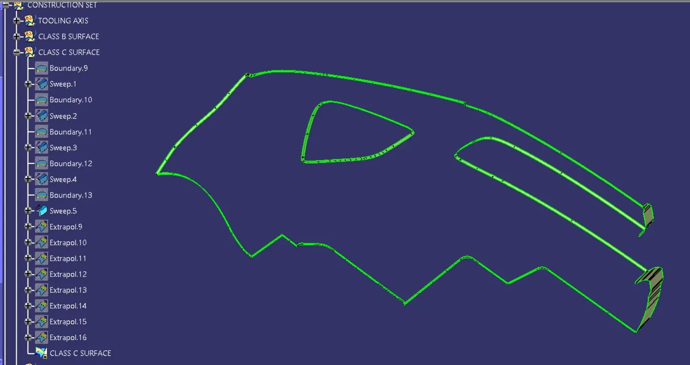
· Using Boundary and Extrapolate command, the Class C surface is created as shown below:
Final Tooling Surface
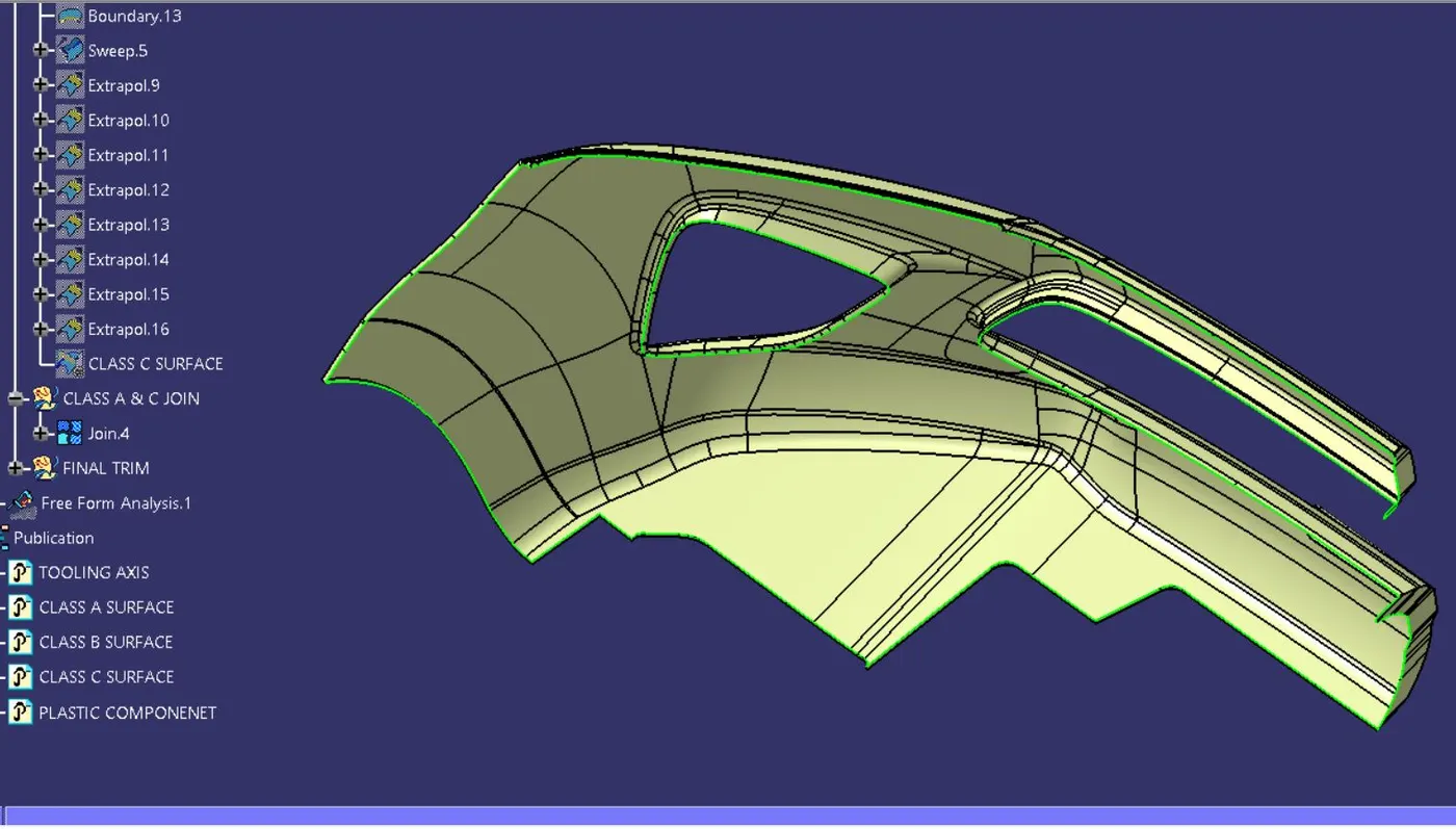
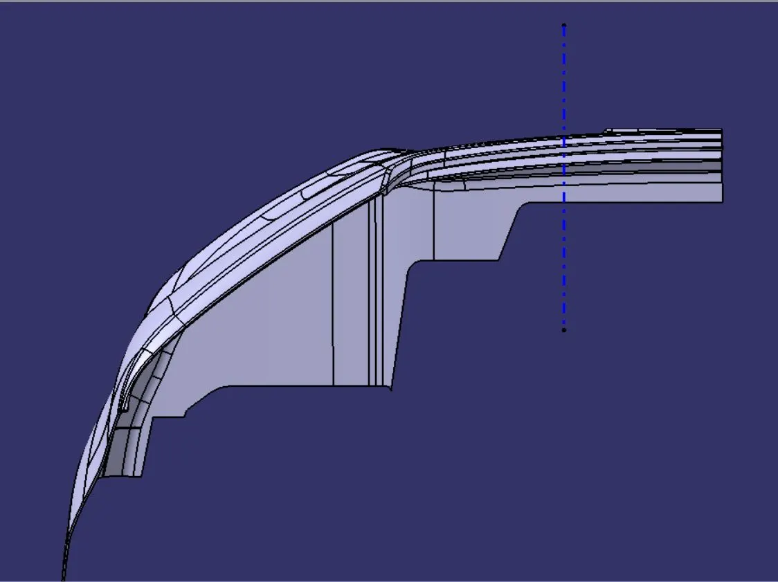
· Now Join Class A & C Surface and Trim it with Class B surface for final Plastic Component.
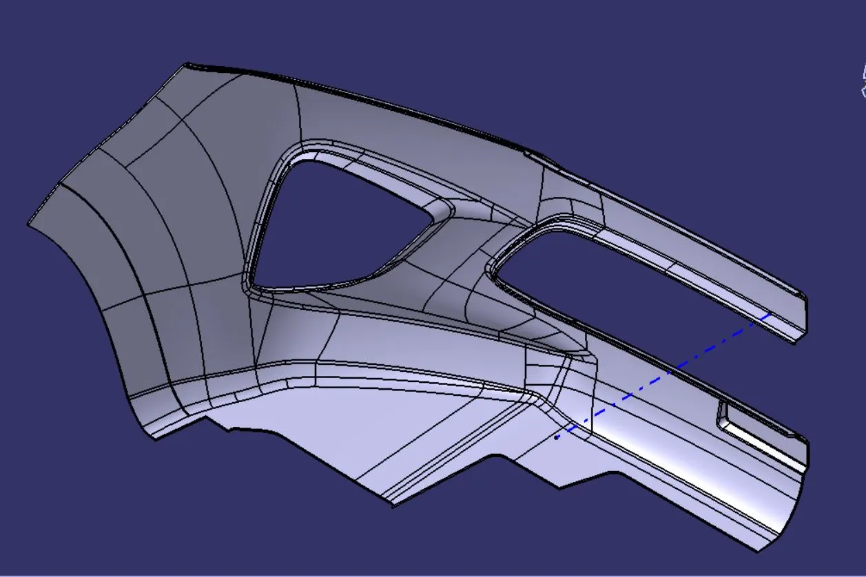
· Now using Trim command all the excess surfaces are trimmed and required final surface is formed as shown below:
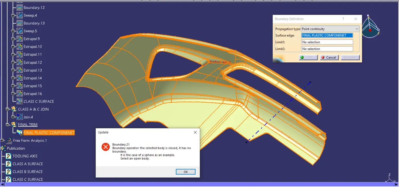
Converting to Solid Body
· After completing the Final surface, shift to Part Modelling interface, now using Closed Surface Command the whole Surface body is now converted into solid Plastic Component.
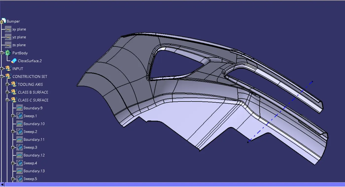
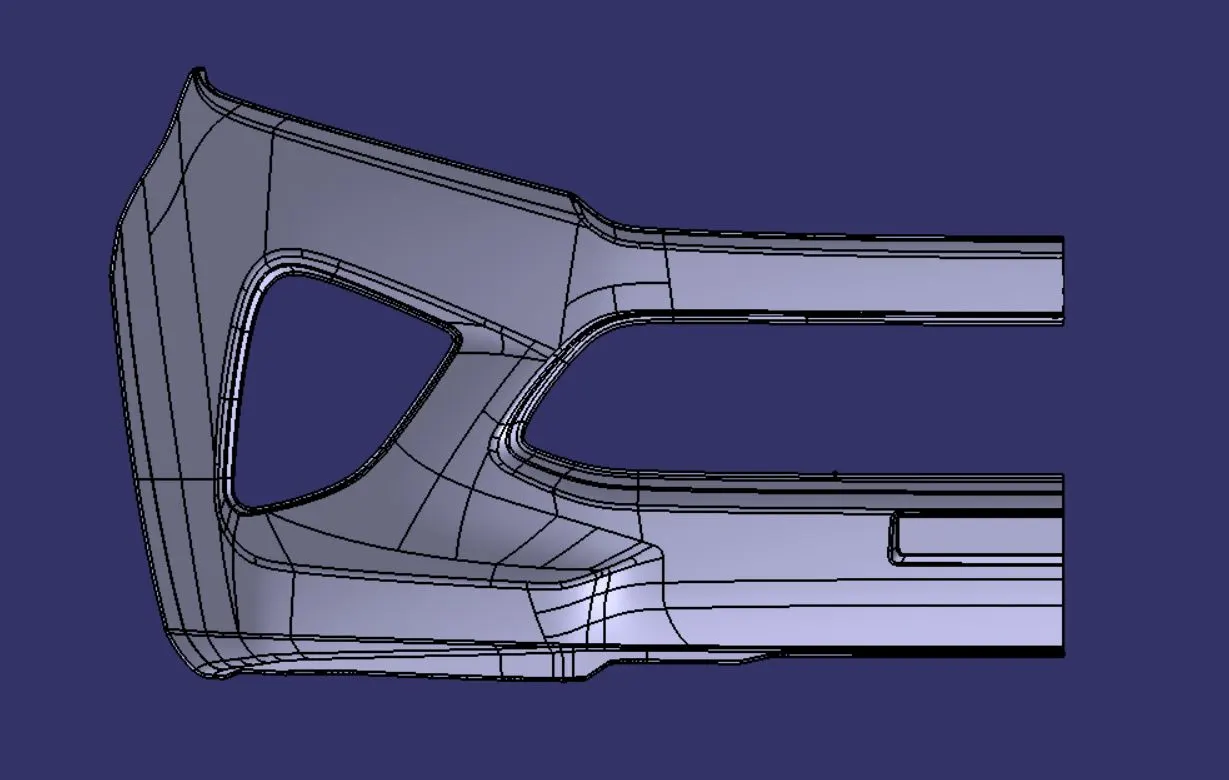
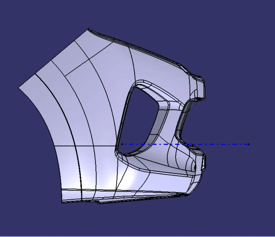
Draft Analysis on Final Plastic Component
· As shown below the Draft angle is under well acceptable range for the Final Plastic Part.
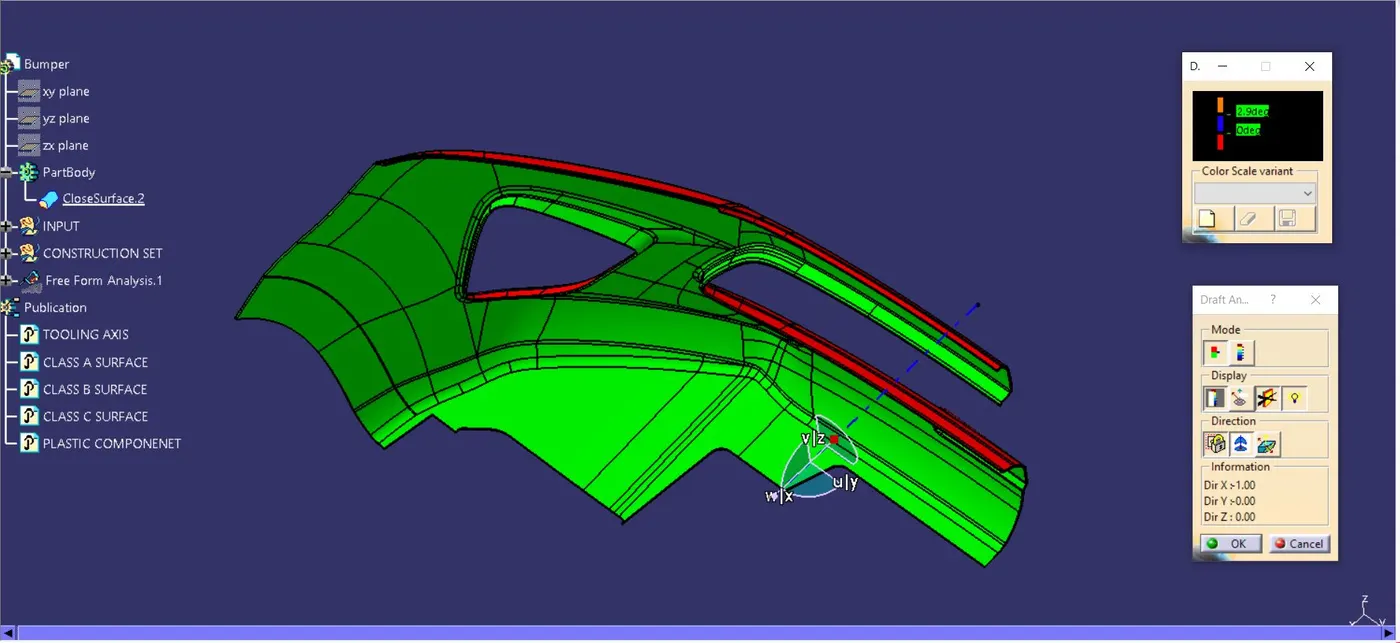
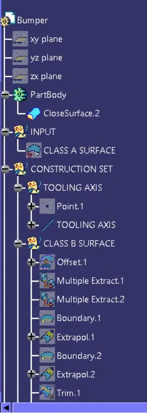
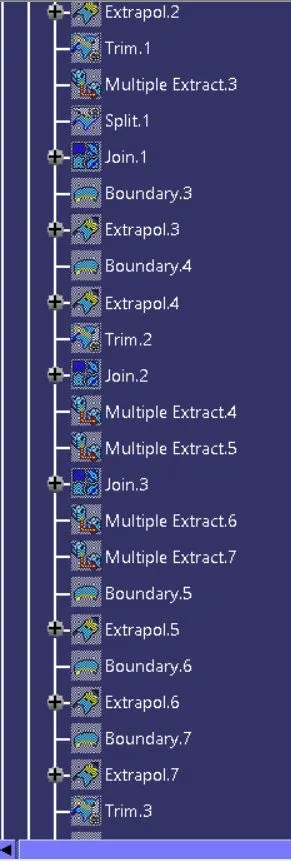
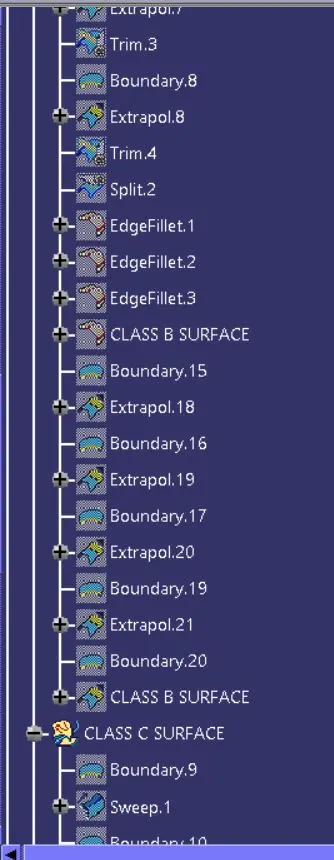
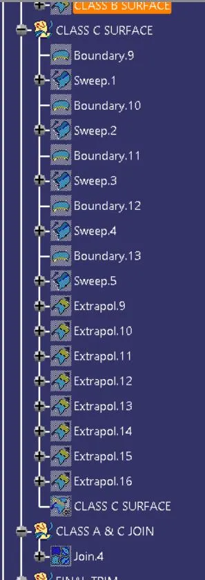
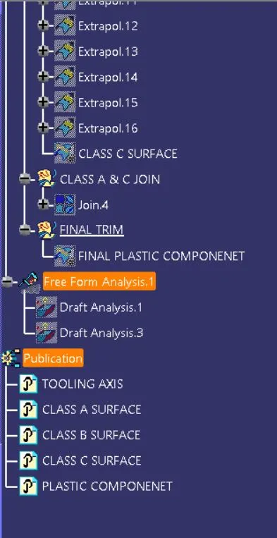
Following are the images of the Tree Structure of the Plastic Component: