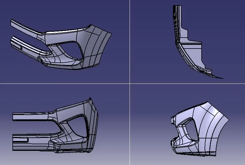
Week 9 - Challenge 3 - Bumper
BUMPER DESIGN
- AIM: - To create the Bumper's Plastic-Component using the Class A Surface that is provided. Desired Thickness of the Plastic Component is 3mm with 3 degrees as the Draft Angle.
- OBJECTIVE: - Firstly, we have to create the required Tooling-Axis for the given Class A Surface while meeting the requirements of the necessary Draft Angle & then perform the Draft-Analysis Operation on the Class A Surface itself. After that, we have to create the required Class B & Class C Surfaces using which we have to create the Final Plastic Component and perform Draft Analysis on it as well.
- DESIGN METHODOLOGY: - Skin data will be provided to us by the styling team. Class-A surface means aesthetic surface. It gives the aesthetic of the component which is created by the styling team and gives to the part design engineer to create the part with all engineering aspects.
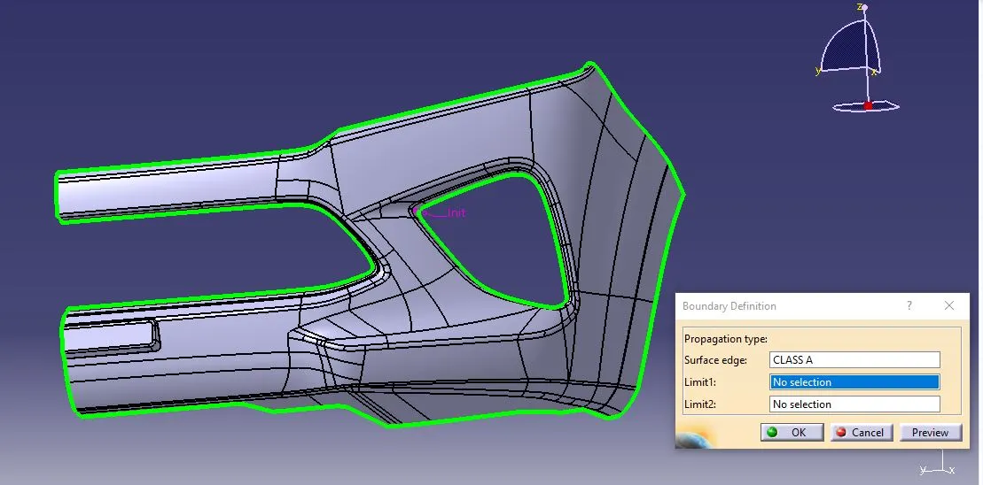
The first step is to check the continuity of the class A surface. This is to ensure that there is no gap between surfaces. If we find any then we should fix that first.
Analyse the class A surface through visual inspection. To make sure that the given surface has no gap in between them. We can check it also with the help of Join or boundary commands.
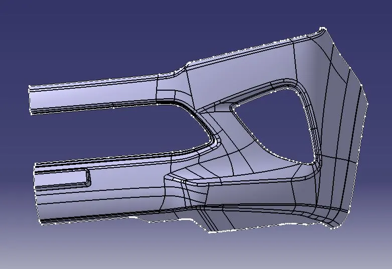
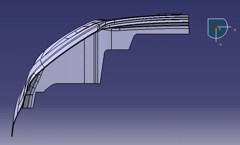
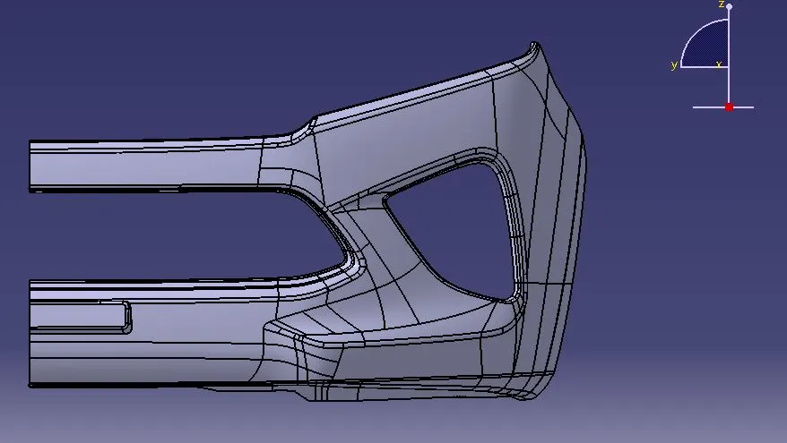
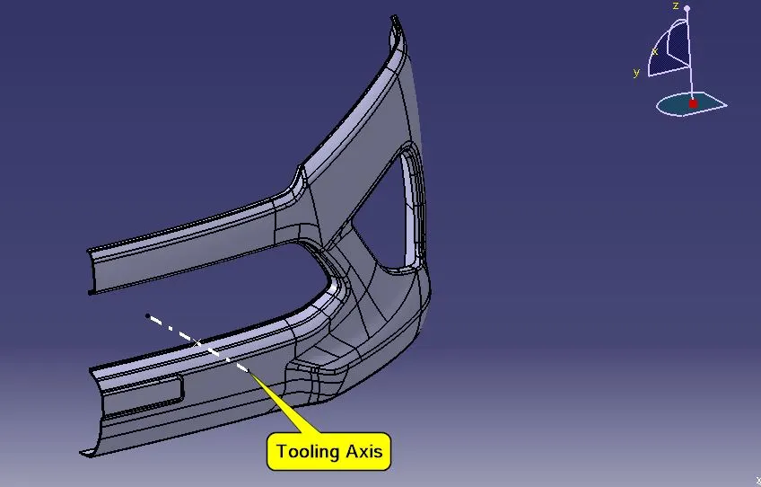
CREATION OF TOOLING AXIS: - Visually inspecting the surface and assuming tooling axis in basic X, Y & Z axes. the hollow portions can be cleared in Z axis easily. So created a dummy tooling axis in X direction by creating a point on the surface then create a line using references created point & X,-direction.
VIEW NORMAL TO THE Y-DIRECTION
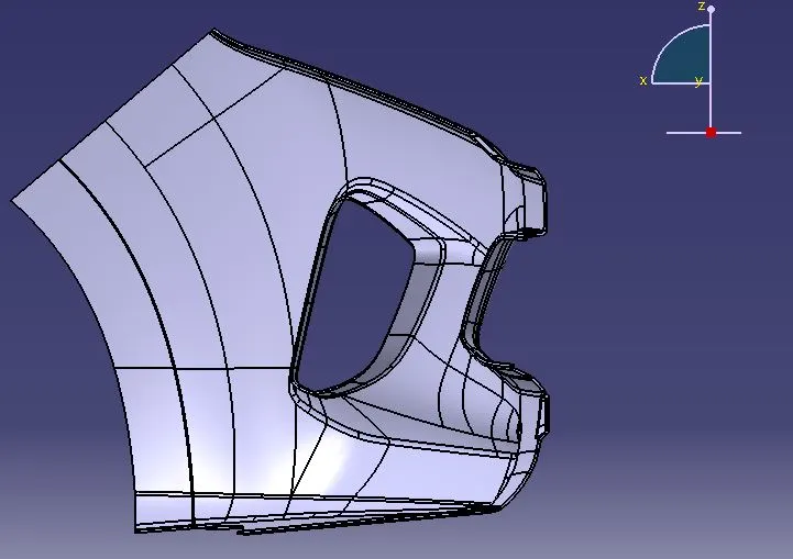
VIEW NORMAL TO THE Z-DIRECTION
VIEW NORMAL TO THE X-DIRECTION
TOOLING AXIS CREATED
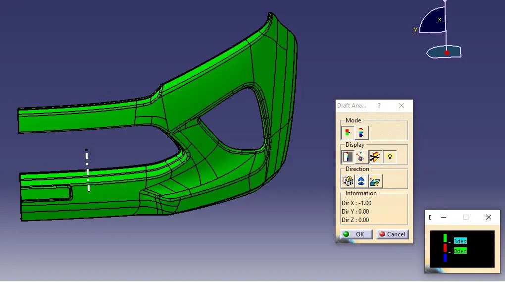
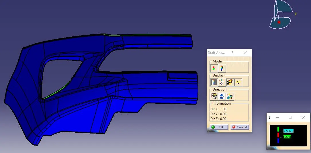
PERFORM DRAFT ANALYSIS ON CLASS-A
The draft analysis technique is used to analyse whether our part model created is manufacturable based on the draft condition applied. To perform draft analysis the view parameters are set to material mode.
Then insert the feature draft analysis select the axis system and drag the axis system to align and coincide with the tooling axis and lock the orientation.
This axis system defines the draft direction according to the tooling axis. Set the minimum value, here it is set to 3 degrees and it will be displayed in green colour. Now select the running point tool to measure the draft angle at various locations.
CREATION OF CLASS-B SURFACE: - The A-surface is offset by 3.00mm as it is the thickness required. The Areas where the B-surface has issues are corrected by closing them using commands like Multi section, Sweep, Offset and extract.
Finally, all the created surfaces are trimmed or joined together with offset surfaces done earlier. This created a single surface which will act as the final B-surface.
B surface created is checked for any gaps or errors by creating a complete boundary.
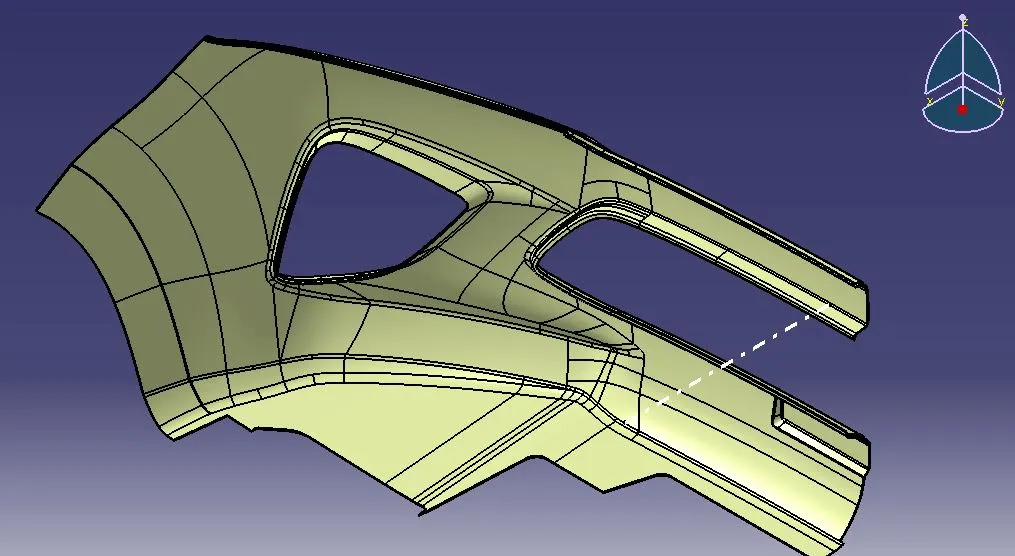
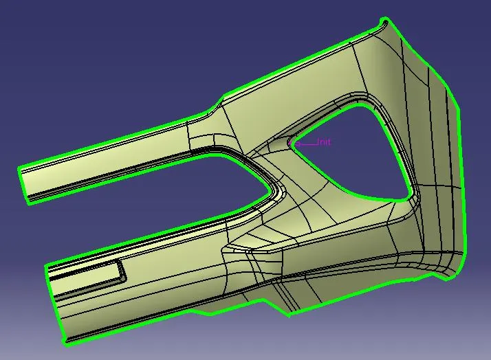
CREATION OF CLASS-C SURFACE: - The A and B surfaces are connected by another single surface which is called the C surface.
It is created by using sweep with A surface acting as the reference surface and curve created from the boundary of the same surface. Sweep with draft direction is also used to create A-surfaces.
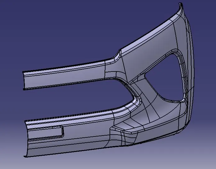
Following is the picture of Class A + Class C surface join together.
CREATION OF CLOSED BODY: - All the surfaces (A, B & C) are joined together to form a closed body.
Boundary is selected and the body is picked. Since an error popped up it can be understood that all surfaces are joined with each other to form a proper closed surface body.
Finally in part design workbench, using close volume it is changed to a solid body.
CLOSED SURFACE (A + B + C)CLOSED SURFACE (A + B + C)
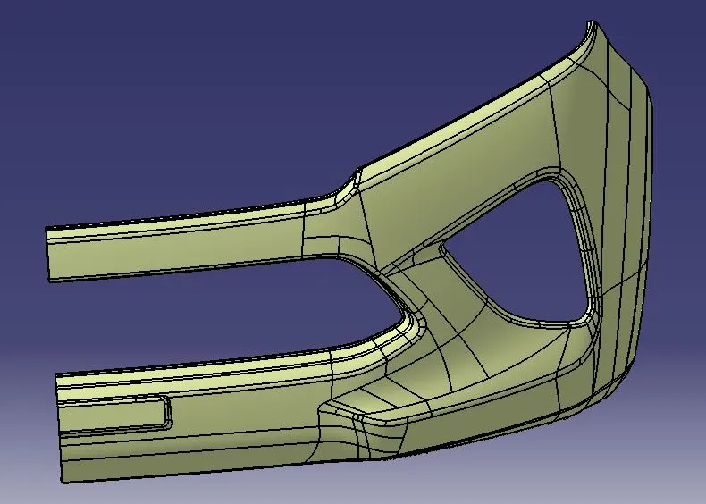
VERIFIED CLOSED BODY USED BY BOUNDARY COMMAND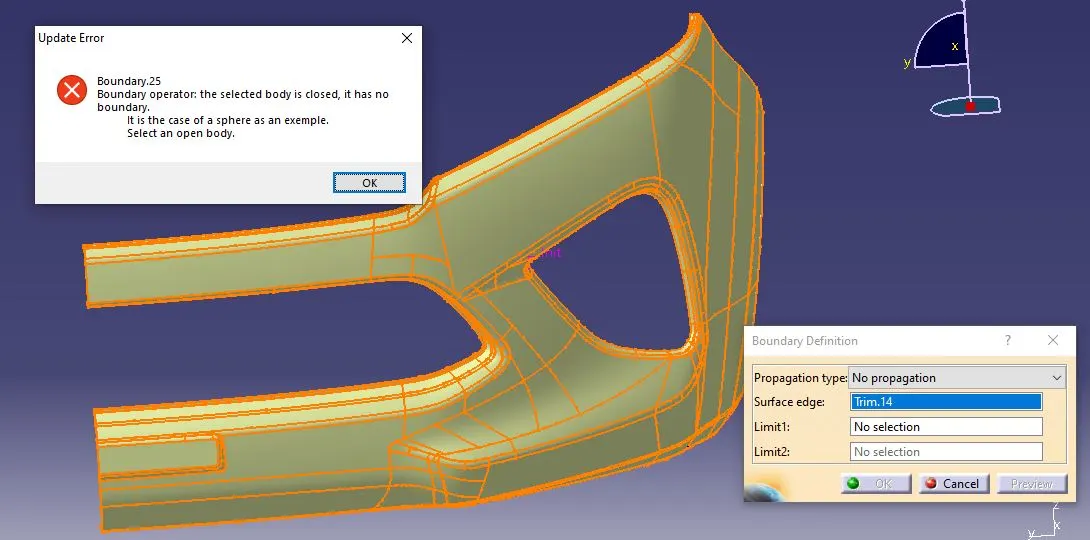
CREATION OF SOLID BODY USED BY CLOSE SURFACE COMMAND
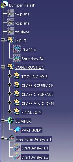
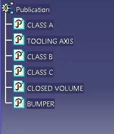
MODEL TREE: - The model tree created shows that all the geometrical sets are named for clarity. The publications of Tooling axis, surfaces of A, B and C surfaces are done. Also, the closed surface body and Volume is published.
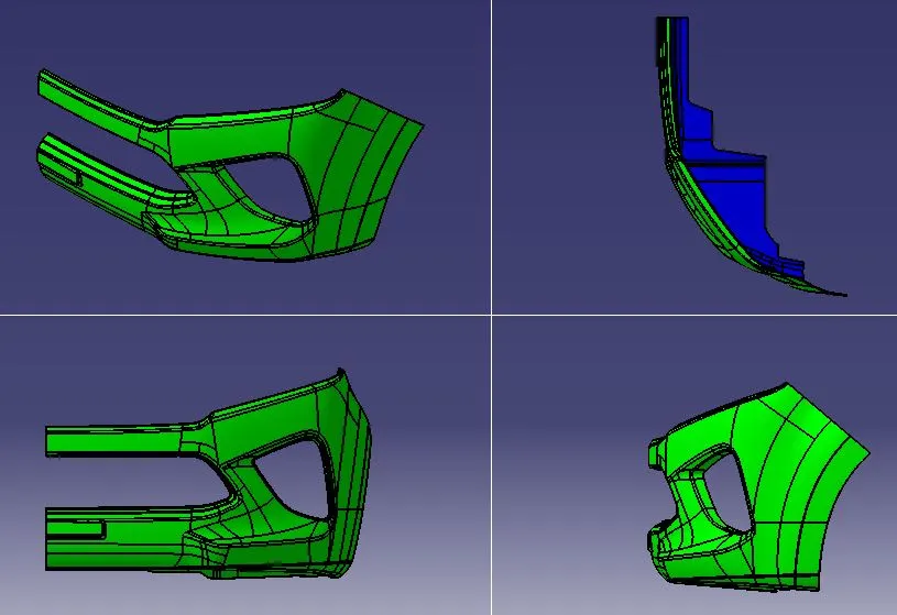
DRAFT ANALYSIS OF PART BODY: - The final solid part body has to be analysed using Draft analysis. This is done to check if all the areas of the body are satisfying the draft angle which is 3 degrees.
A draft angle is a taper applied to the vertical walls of the injection-molded component to assist with releasing the part from the mold.
Draft angles are a required feature of injection-molded custom parts. A functional part for injection molding has to have draft angles that face both the cavity and core sides. This will reduce the risk of damage to the parts and ensure that they can be ejected from the machine.
The Bumper body is checked using Analysis and images for it are shown below.
DRAFT ANALYSIS (VIEW-1)
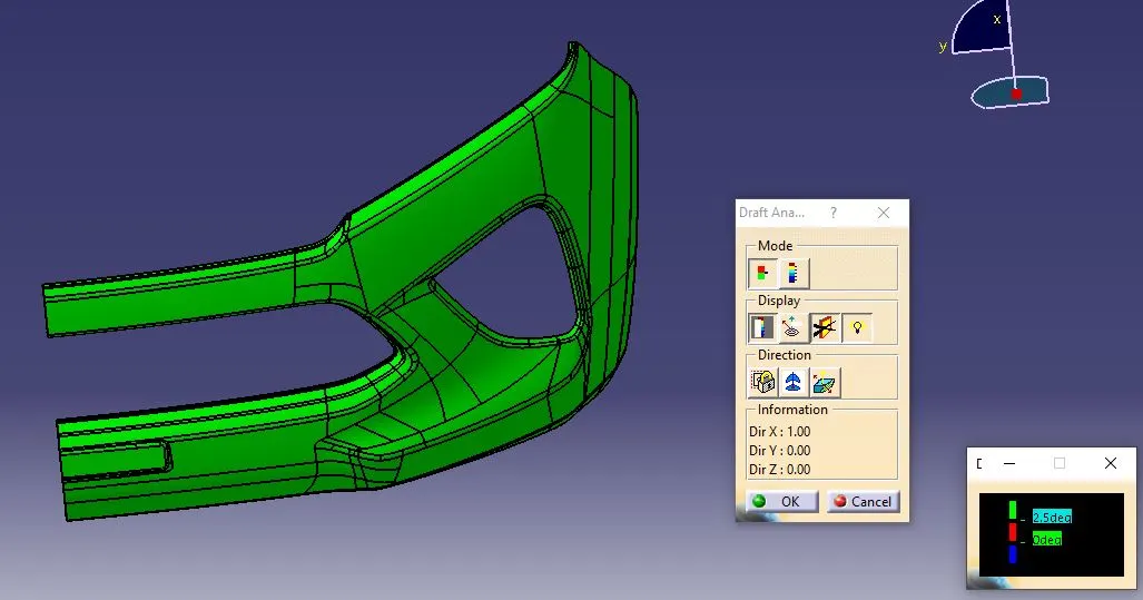
DRAFT ANALYSIS (VIEW-2)
DRAFT ANALYSIS (4 VIEWS)
PART BODY (4 VIEWS)