Week 9 - Challenge 3 - Bumper
AIM:- Create the Bumper Plastic component using the given Class-A surface. To begin with, the tooling axis for the given Class-A Surface should be created meeting the requirements of the draft angle and at the end perform the Draft analysis on the model.
The thickness of the component is to be 3 mm.
NOTE:
- Tree Structure
- Ensure Proper Tree Structure
- Geometrical sets should have a proper name based on the sketches present inside of it
- All the sketches should be created under the Geometrical set
- Use the Close Surface feature to make a solid body from the surface.
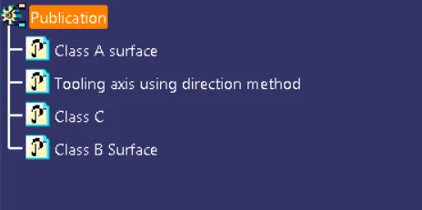
- Publications: Use the publication option and publish the below
- Tooling Axis
- Class A, B, and C surface
OBJECTIVES:
Create the Tooling Axis
Create the Class B and C Surface
Create the Close Surface
Perform Draft Analysis on Class-A and Final Part Body
Minimum Draft Angle = 3 degrees
INPUT:- CLASS A SURFACE
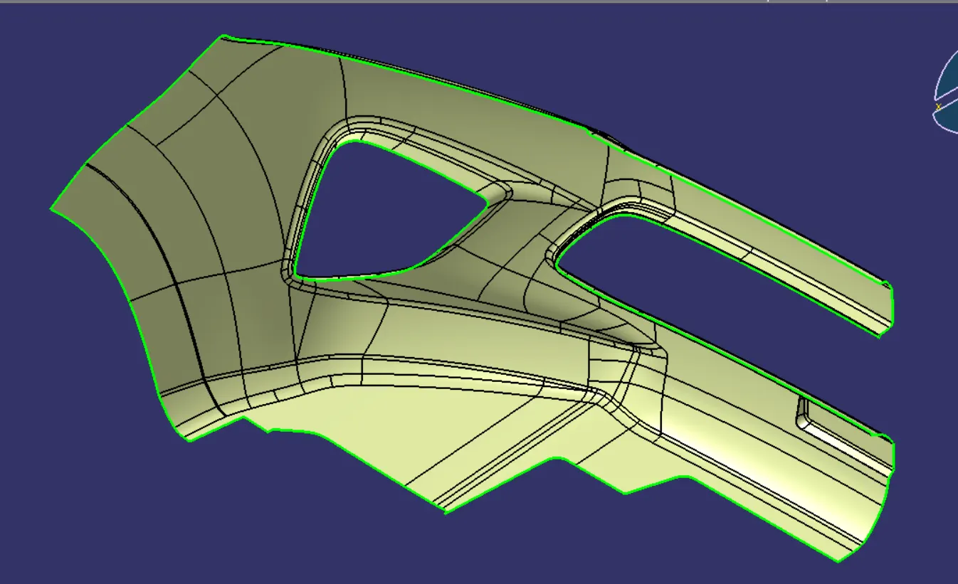
We receive class A surface as our input to create class B and C surfaces, trimming and joining them together to form a close part body. Class A is surface doesn't have thinkers to it, it is just an aesthetic surface that is designed in a different design software called Alias. Class picture is shown below -
Before we start to work on the class B-surface creation we check the class-A for any gap or discontinuity between the faces by using a boundary command in Catia.
Tooling Axis creation:-
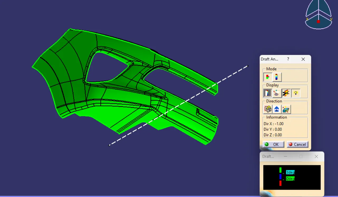
We check all the x,y, and z directions for the best tooling axis and in which direction the class-A surface has maximum perpendicular surface we choose that direction as our dummy tooling axis. We carry out a draft analysis of Class-A surface along our dummy tooling axis and check whether the class-A clears our dummy tooling axis if it clears so then we make the dummy tooling axis our main tooling axis and start working further.
Class-A surface draft analysis:-
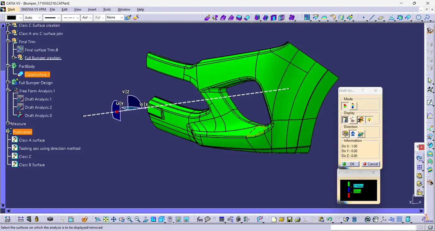
Picture of draft and tooling axis- The color code Green on Class-A has more than 3 degrees of draft along the tooling axis we define for it to manufacture. the tooling axis and surface is cleared to work further to create class-B surface.
Class-B surface creation-
Class B is created by offsetting class-A by 3mm as our part thickness is 3mm. The off-setted surface has multiple missing surface patches as shown-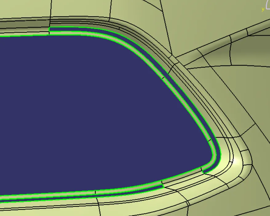
we use different commands in Catia to fix these gaps and create a perfect class-B surface. The commands/operations we used are-
- Off-Set
- Extract, Multi-Extract (with Complementary option)
- Join ( with Sub elements to remove option)
- Boundry
- Extrapolate
- Trim and Split
- Edge-fillet
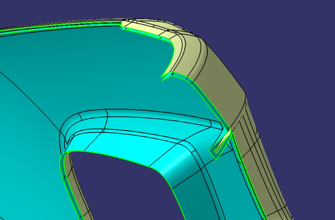
Complete class B is shown below in sky blue color-
Class-C surface creation-
We created a boundary of a class-A and swept it along the tooling axis using the sweep command in the draft direction and reference with the surface. Class A is used to create boundaries because we can chop off or make any changes in class A. The draft given is 3 degrees. The draft is provided in a 3-degree outward direction so that the parting line lies in between Class-B and C surfaces.
Boundaries picture- It has multiple boundaries extracted individually as the surface has sharp edges at some points.
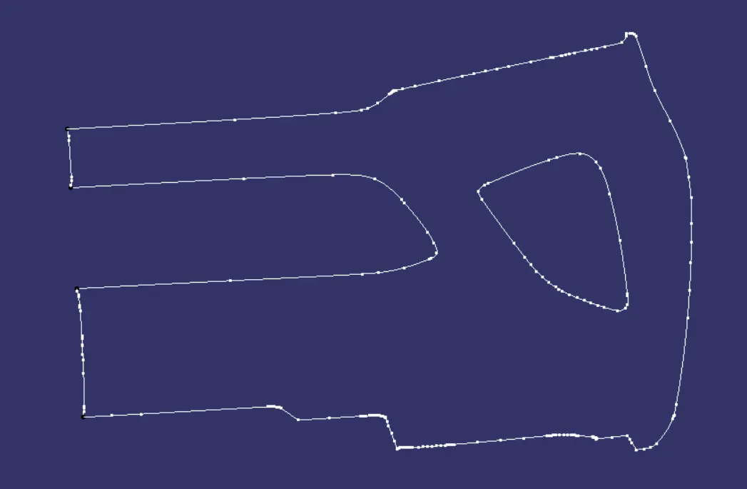
Class-C surface picture- Class C is in a perpendicular direction from the class-A surface.
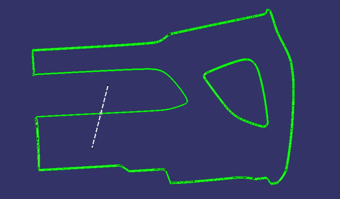
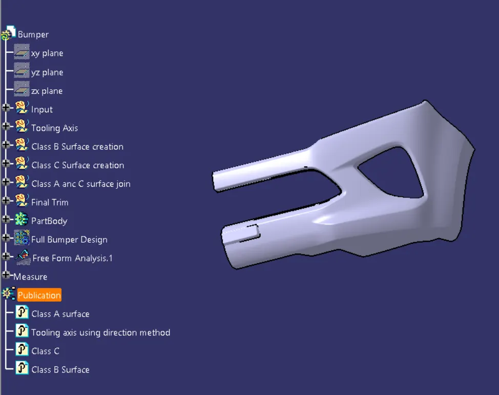
we then published all the 3 classes of surface A, B and C along with the tooling axis as shown below-
Joining Class A and C surfaces- Class C is in blue color
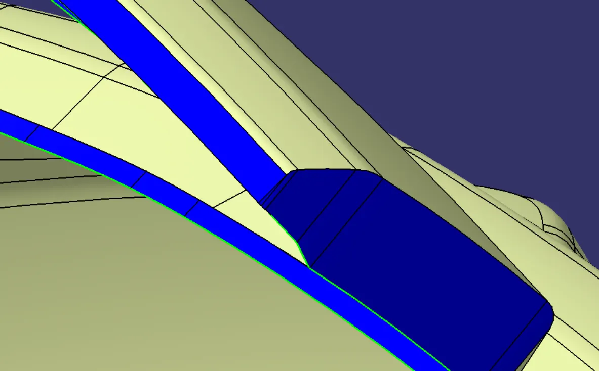
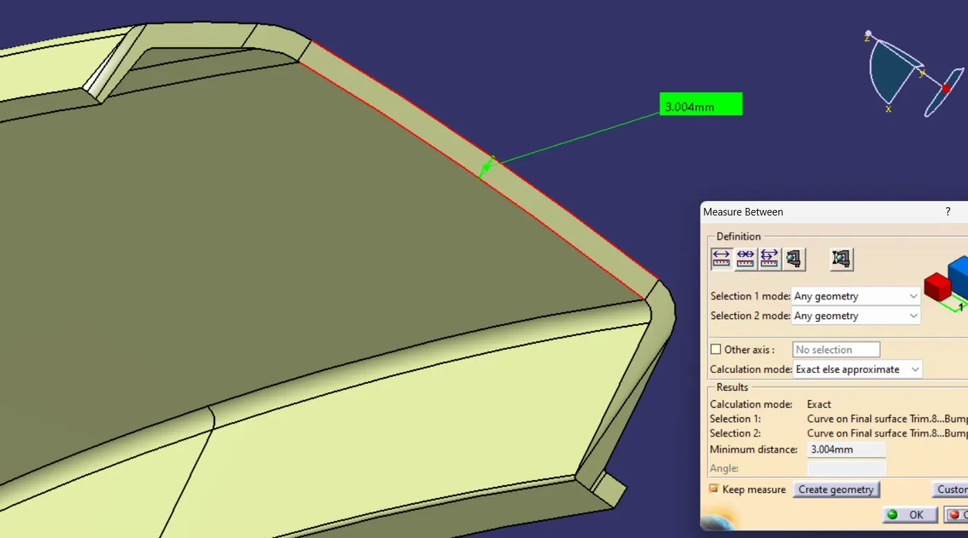
After final trimming, we got our final closed surface as shown- thickness between class A and B is approx. 3 mm as shown.
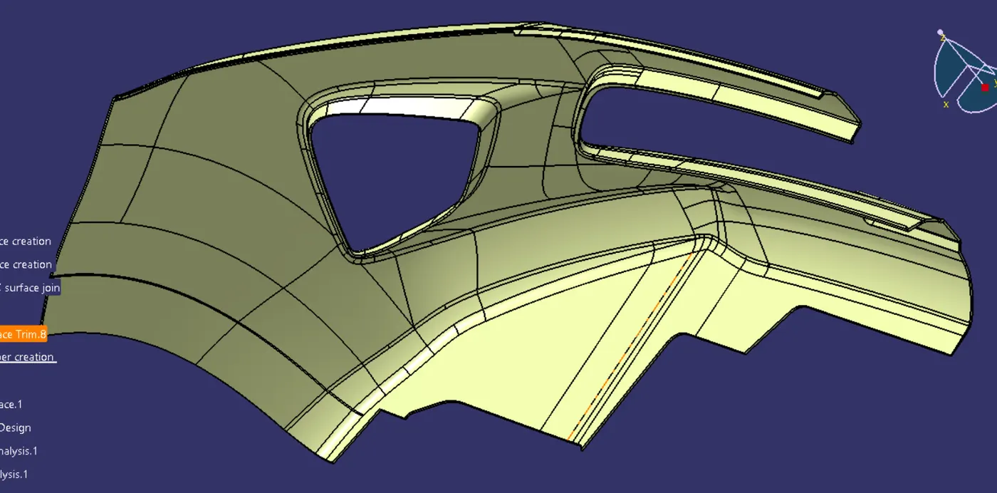
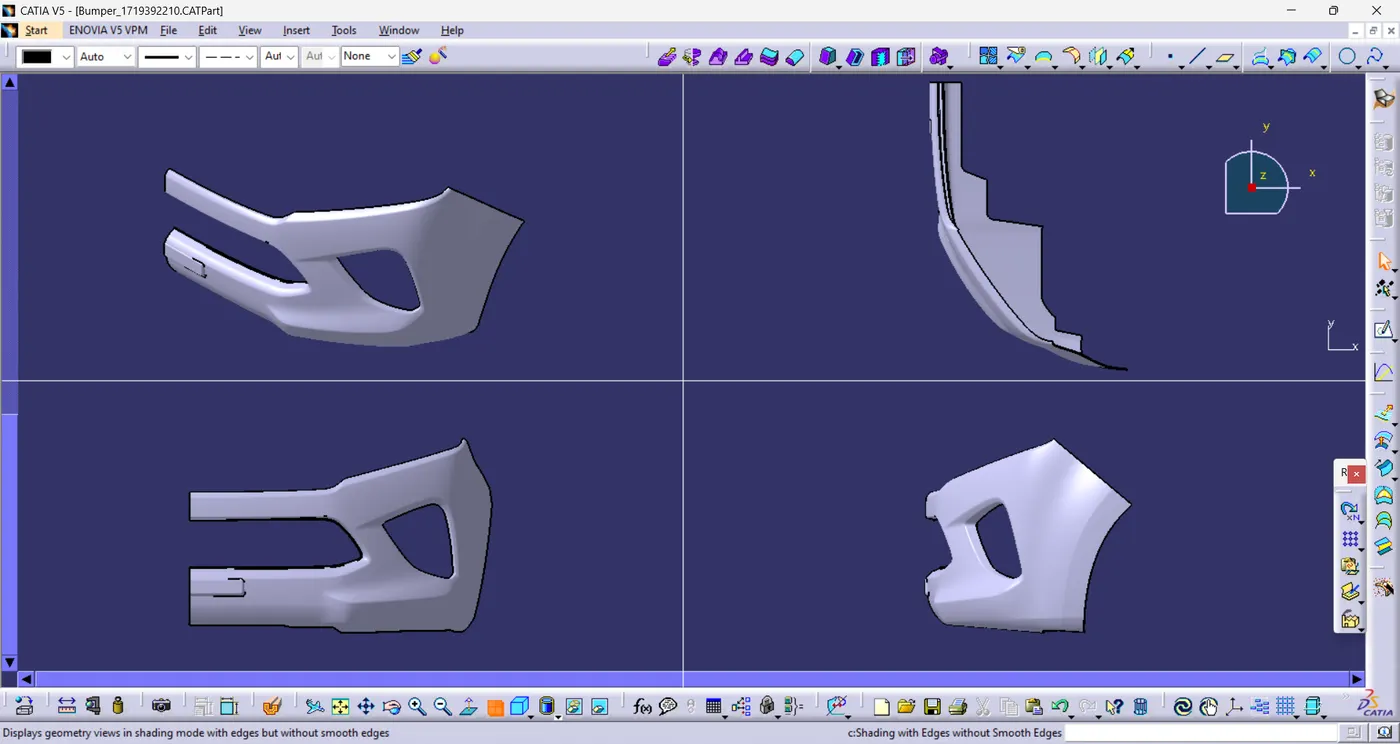
Closed Part Body- using the close surface command in part workbench. pic is shown in different views, Screenshots of the solid model with the proper color code of the draft angle in various orientations (Isometric, Front, Side, and Top View).
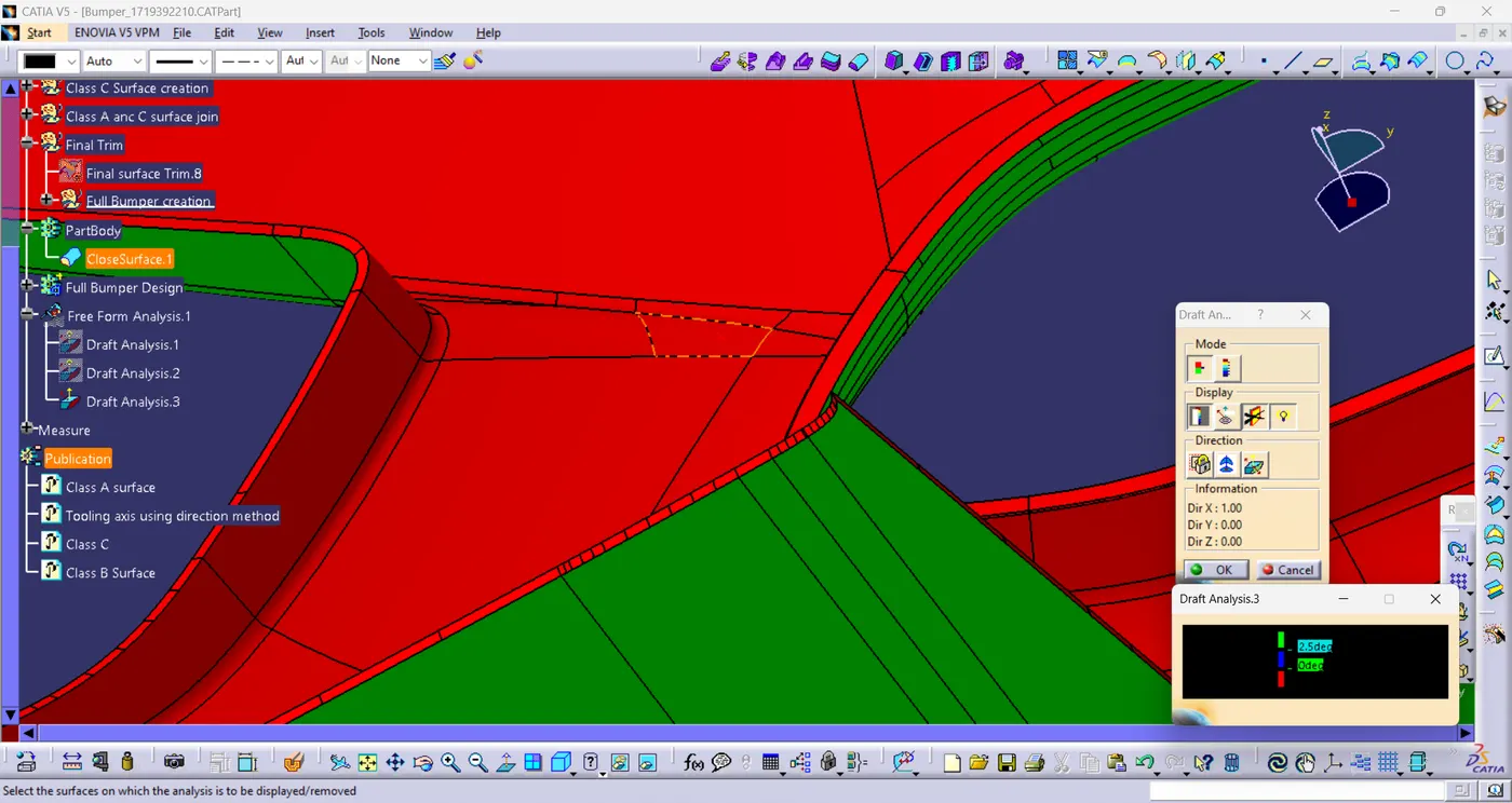
Draft analysis of the final part body- where the red color starts is where the parting line is this is why it shows a different color.
I have also created a complete full Bumper design without B-side features by split, Symmetry, and join commands. 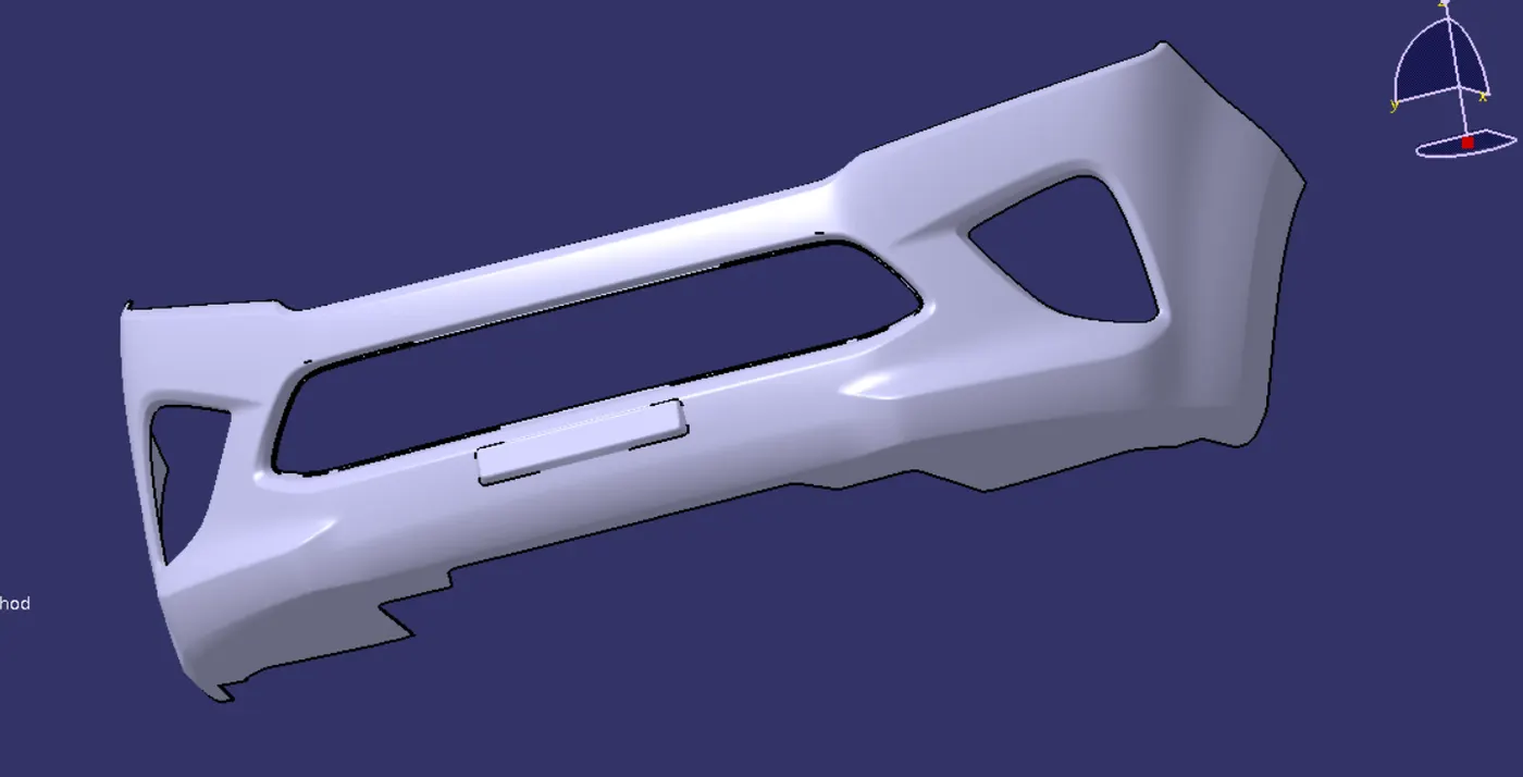
I have mentioned all the difficulties that I faced and their solutions while designing the part in separate geometrical sets included in the part file.
Spec Tree-
Thank You.