Week 9 - Challenge 3 - Bumper
AIM : To create the Bumper Design Plastic component through the given Class-A surface.
Objective
- To create a tooling direction.
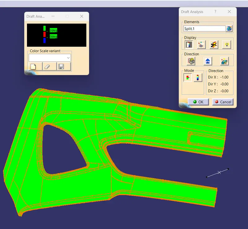
- To perform draft analysis for given A-Surface and prepare the final close body.
- To design the Bumper plastic component by creating the B-Surface and C-Surface using the given Class-A surface.
- Take the Thickness of the component to be 3 mm.
Introduction :
The input of the product designer is in the form of the A-class surface. The job of the product designer is to create the B and C surfaces keeping all the aspects for the mold.
Class A Surface is
- Visible surface and aesthetic look.
- Surface with textures.
- Surfaces provided by customer(OEM).
- Don't have any features like(rib, snap, bosses, etc) on class A surface.
- Class A surface is made from scanned data with different software like alias etc.
- Surfaces which are having CURVATURE CONTINUITY IS CALLED class-A.
Class B surface is
- Invisible Surfaces.
- Surface mostly don't have textures.
- Surface needs to be created according to the class-A surface.
- Having all features(Rib,boss,snap etc) in B-side surface only.
- Surfaces which is having TANGENT CONTINUITY IS CALLED class-B.
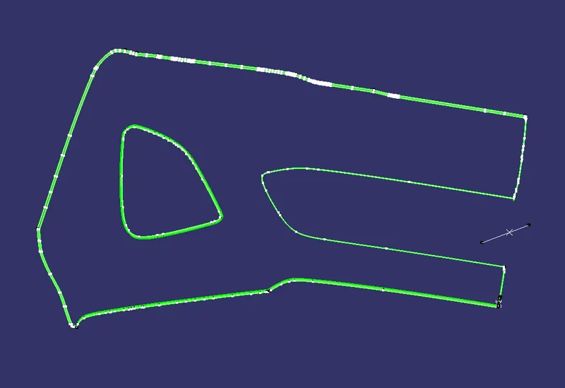
Class A Surface : Check the connectivity of the Class A Surface Ensure that there is no gap between the component, using join command. We can visually check it or by clicking boundary command. It has a boundaries outer. Therefore first check completed.
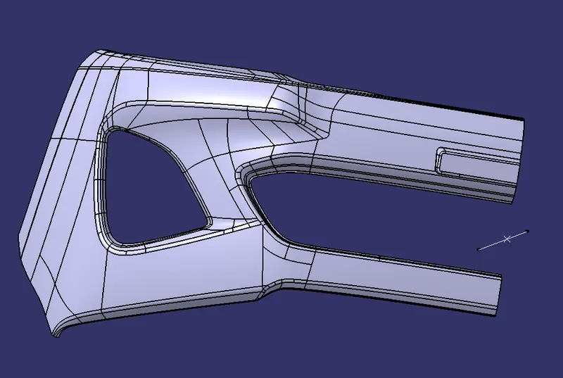
Below fig 1 shown the given A-class surface.
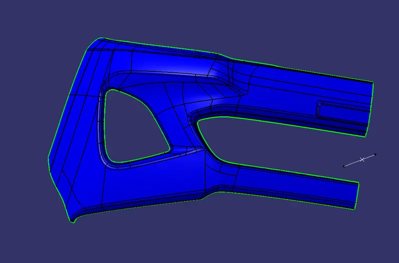
Fig 1.
The given A-Surface having No gap as above fig shown. Hence boundary generated at the edges.
Procedure :
Tooling Direction for Plastic Part : Tooling direction is main consideration for plastic part and mold parts because it defines movement of mold part and possibility of plastic part to come-out from mold part (Core and Cavity).
- In Molding machine arrangement is given to open the mold along a direction which is known as Tooling Direction.
- In other words. The mold is built from two separate halves (Core and Cavity) and tooling direction basically define the direction of mold pulls apart.
- Tooling direction is known as primary direction.
Preparation of Tooling Direction
While creating the tooling direction in given class A surface. Chose the one suitable Base and Side wall and draw the line direction of axis. as shown the below fig 1.1.
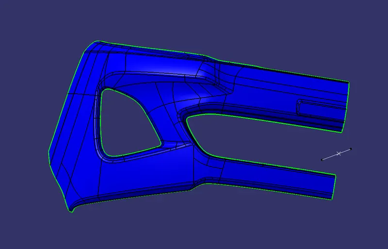
Fig 1.1.
While preparing the tooling direction i followed method is chose the Centre of Gravity. Which is help us to fing the centre point, thene draw the line with the help of point and one no platr plat surface. Hence we consider the final tooling direction.
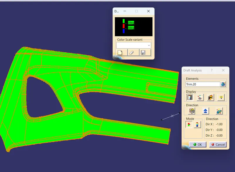
Below fig 1.2 shown the A-Surface Draft analysis.
Creation of B-Surface: Is created with help of A-Surface by using the Off-set,Trim command,Multi Section,Sweep and Fill command. Below fig 1.3 shown B-Surface.
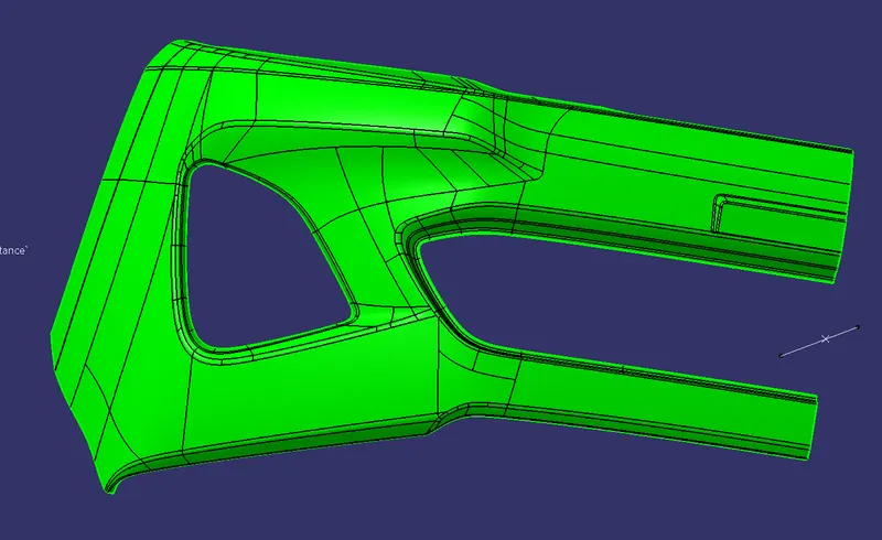
Fig 1.3.
The above fig 1.3 shown the steps followed by the creating the B-Surface. Finally i checked gap and there is no gap.
Creation of C-Surface: Is created with help of A-Surface by using the Sweep and Boundary command. Below fig 1.4 shown C-Surface.
Below Fig shown is the Close Surface .
Below fig shown the joing of A-surface and C-Surface with Draft analysis.
Conclusion : The Bumper is created with consedering all Design Methodology.