Week 9 - Challenge 3 - Bumper
Bumper Challenge
TOOLING AXIS
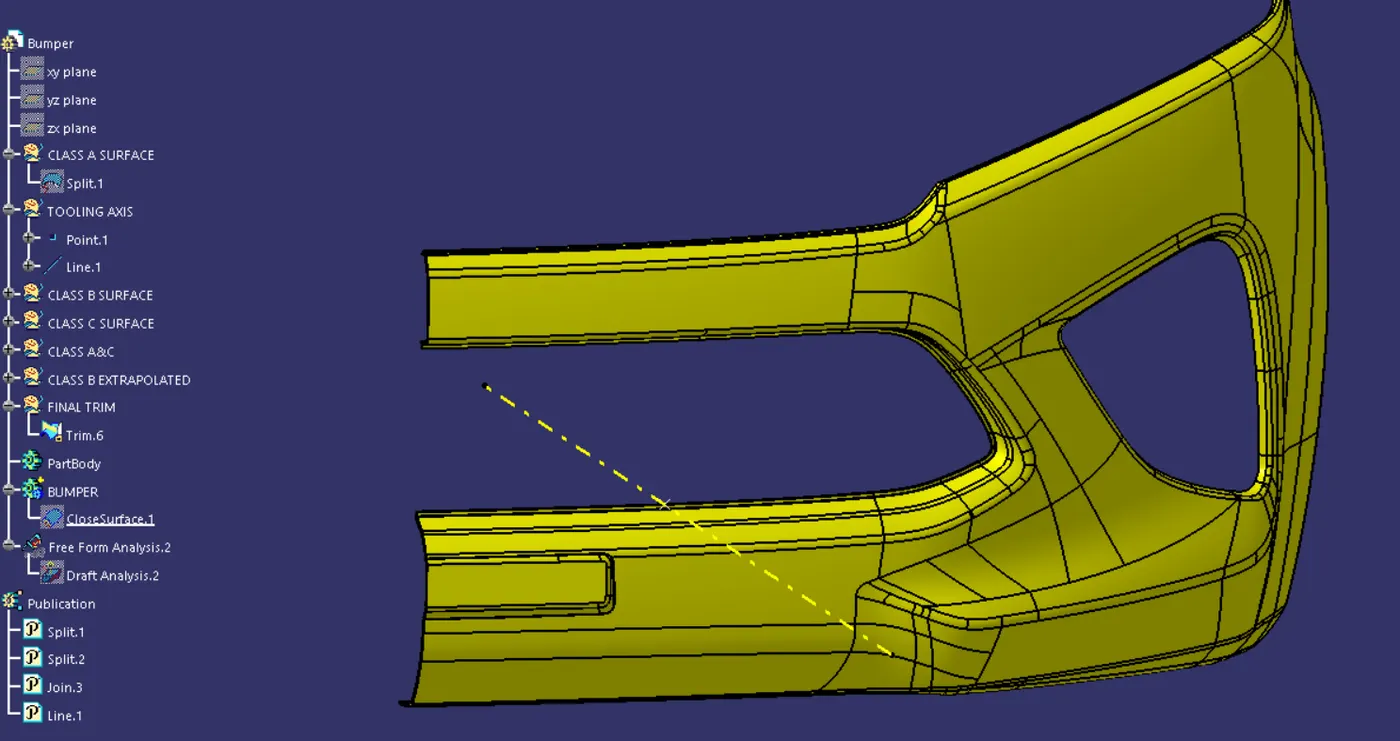
The direction in which the mold or the core and the cavity opens is called as the tooling axis.
Class A Surface
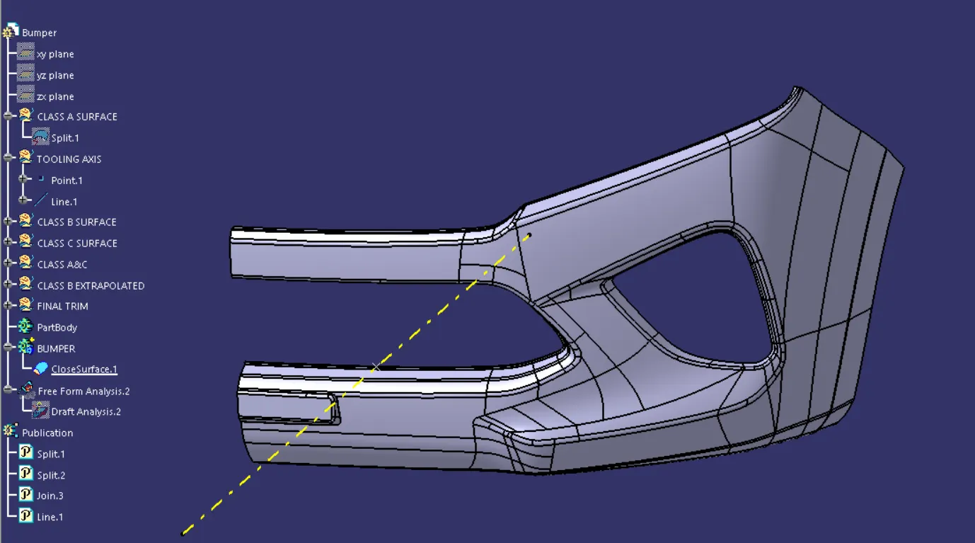
Checking the connectivity by using the boundary or the intersection feature.
Class B Surface
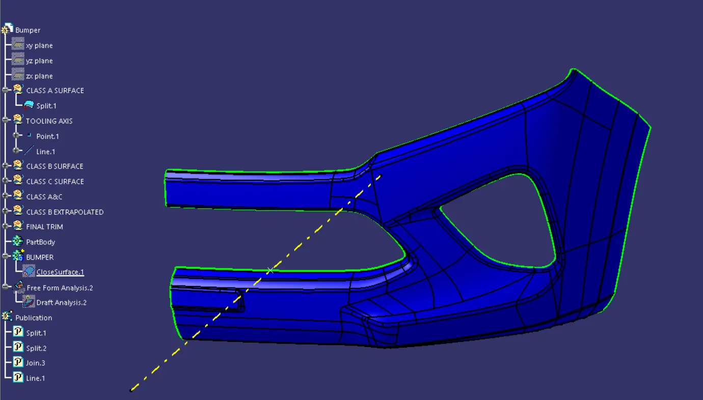
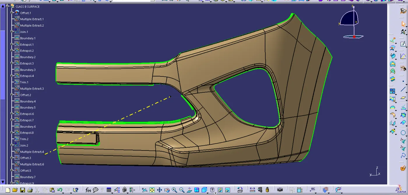
Created by extracing the walls, bezel and the base, untrimming it, extrapolating and offsetting it by the given thickness before triming it all together.
Class C surface
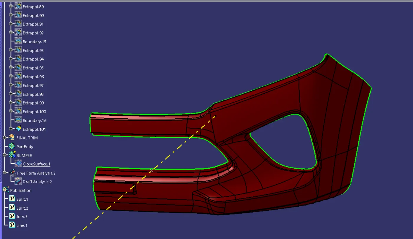
Created by sweeping the draft by direction method, where with the boundary of the class a surface is used as the guide curve along with the tooling axis we are able to join the class A & B surface together.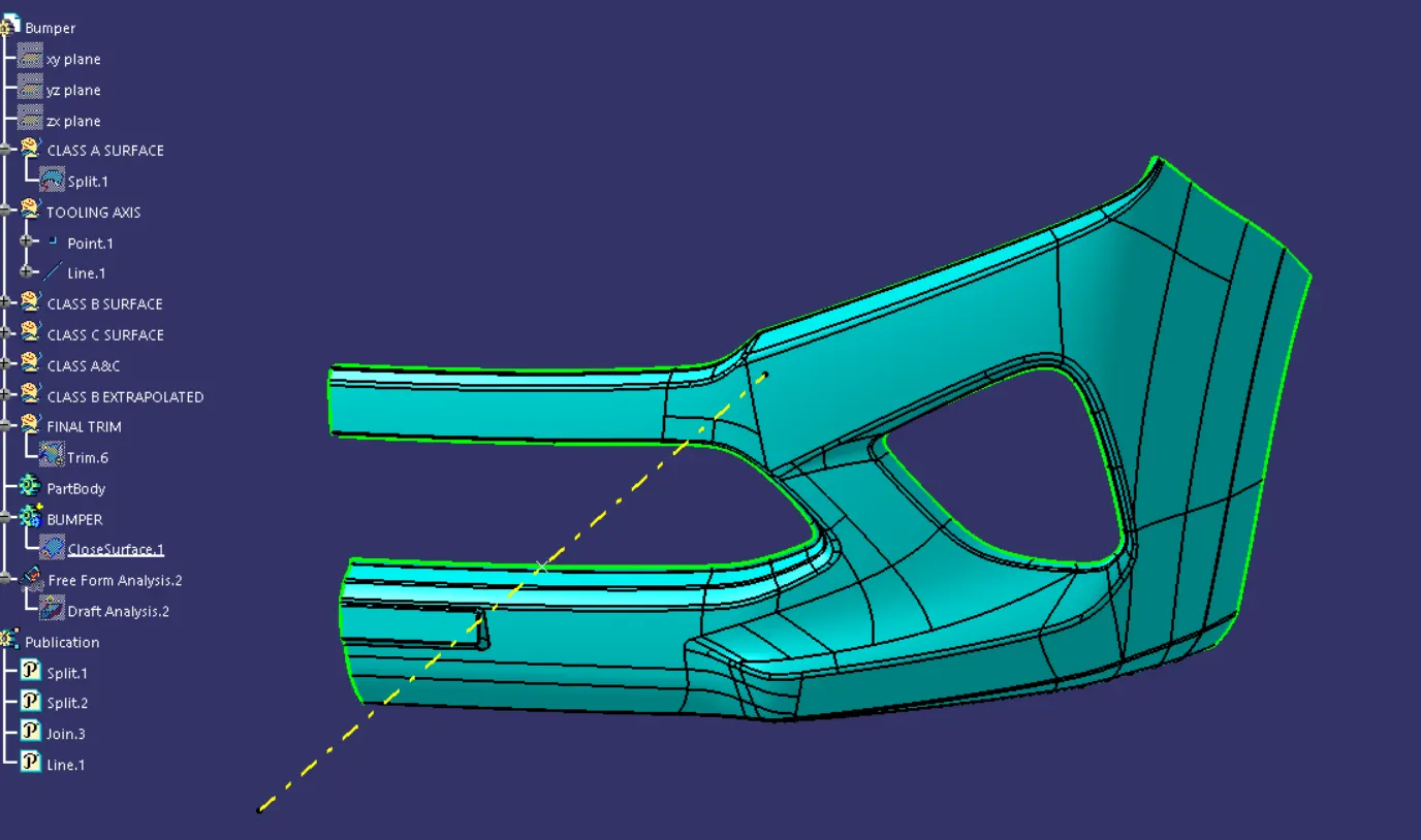
Step 1
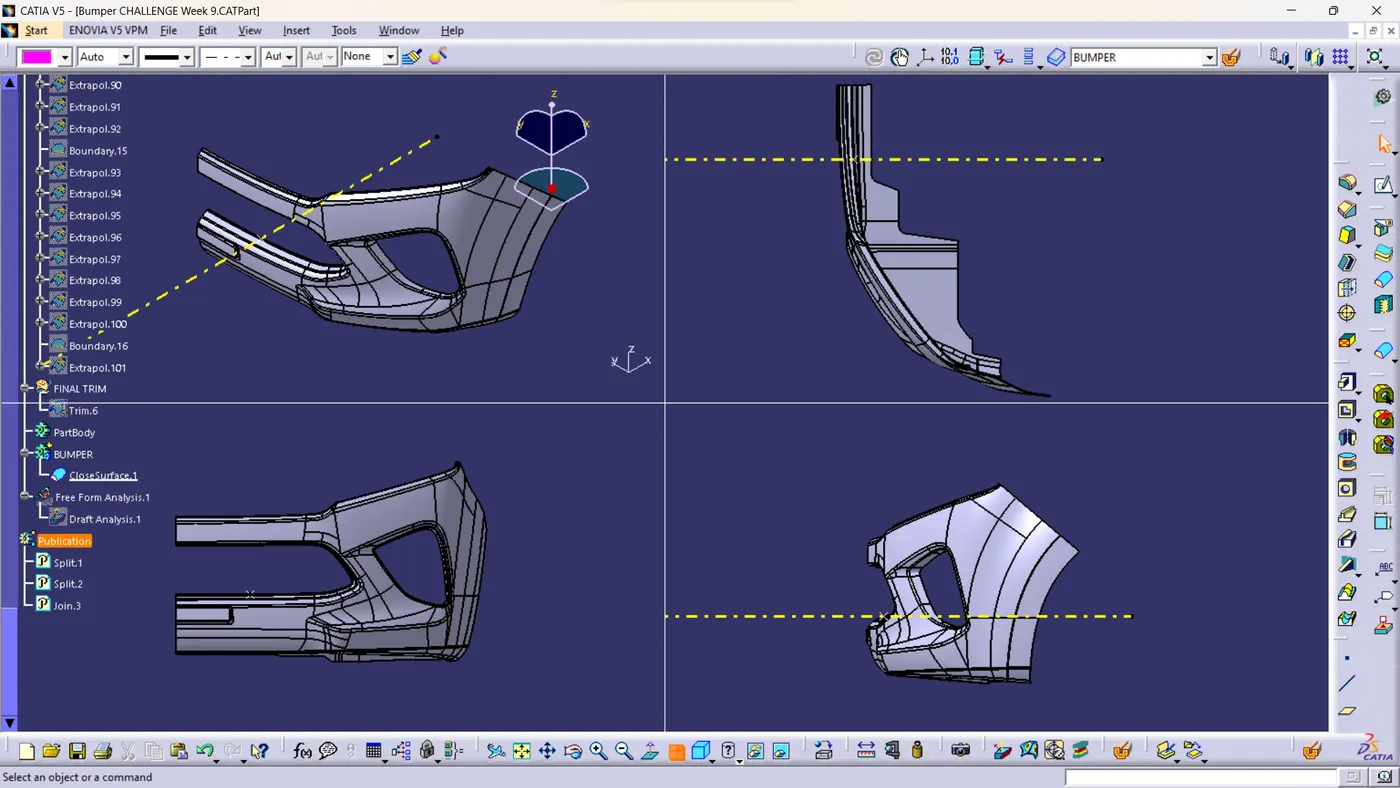
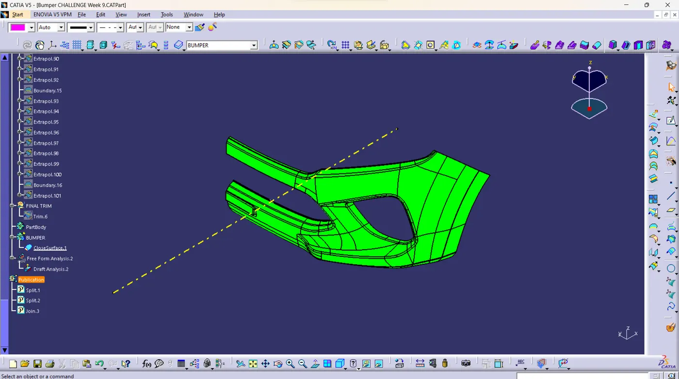
We checked the view through different directions and chose a point were it would draft the entire Class A in green and upon choosing a point a dummy tooling axis was created there and to cross verify we checked it with the draft analysis method and checked for an all green part surface upon draging and placing the compass on the dummy axis, thus this axis was considered as the Main Tooling Axis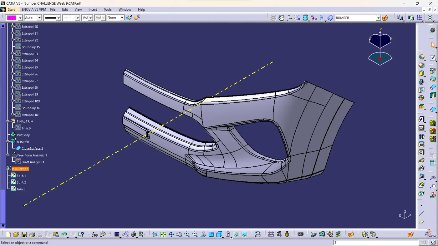
Step 2
We directly offset the entire Class A by the given thickenss of 3mm, the Class B had a lot of the edge fillets missing upon doing so, now with the help of Multiple extracts we started to define the boundary and continued to Extract-Extrapolate-Trim. It was done for the bumpers top edges the number plate section and the grill area and the extra extrapolated areas which were not removed when trim was used these were removed using the split with the plane as the reference command. After this we gave the edge fillets which was determined using the three point circle command.
Step 3
To create the class C surface we at first took the Class A Surface and started to defined the boundary using the boundary command and later used the sweep Commands Using the With reference of the curve and direction, where the curve was the defined boundary on the class A surface and the direction was the tooling axis. We gave a 3 deg outward draft and increased the length as required and we also used the sweep command with the reference as the surface command where the angle was 90deg and required length was given. Once the Sweep area was created we Started to Extrapolate the surcafe and trimmed all together except for the fog lamp section as it was a seperate area, we then Joined the Trim and the Class A surface to get the Class C Surface.
Step 4
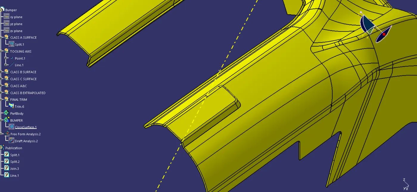
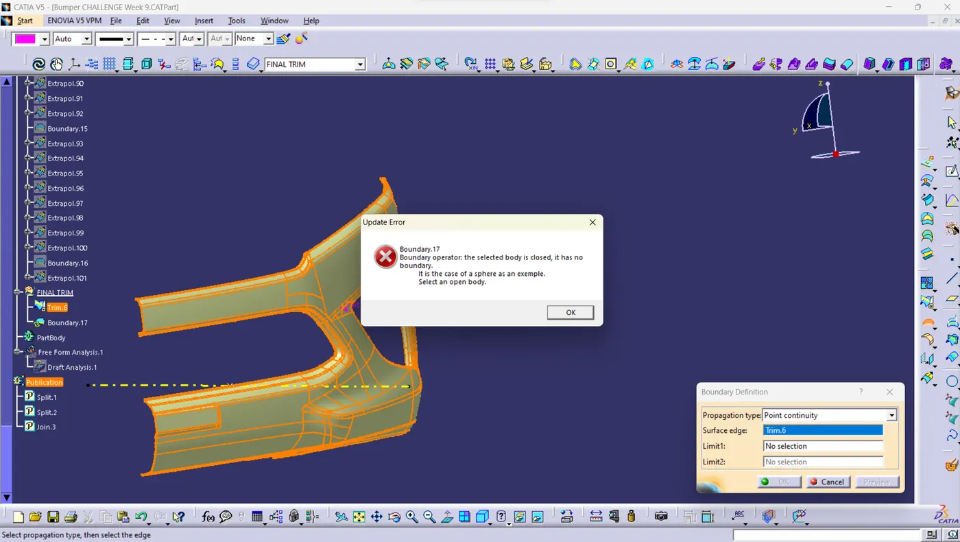
We then extrapolated the Class B edges so that it intersects with the Class C Surface and did a final trim, if there are no openings left the trim takes place leaving a closed structure. now to close this surface we take this surface in the part workbench where we use the Close Surface command to close this Structure, we once again recheck the result using the draft analysis by dragging and placing the compass on the tooling axis. So upon recieving a total green structure we conclude the challenge.