Week 10 - Challenge 1- Attachment Feature Creation (Ribs & Screw Boss)
Engineering feature Ribs and Screw Tools Creation for Door Handle
TOOLING AXIS
The direction in which the mold or the core and the cavity opens is called as the tooling axis.
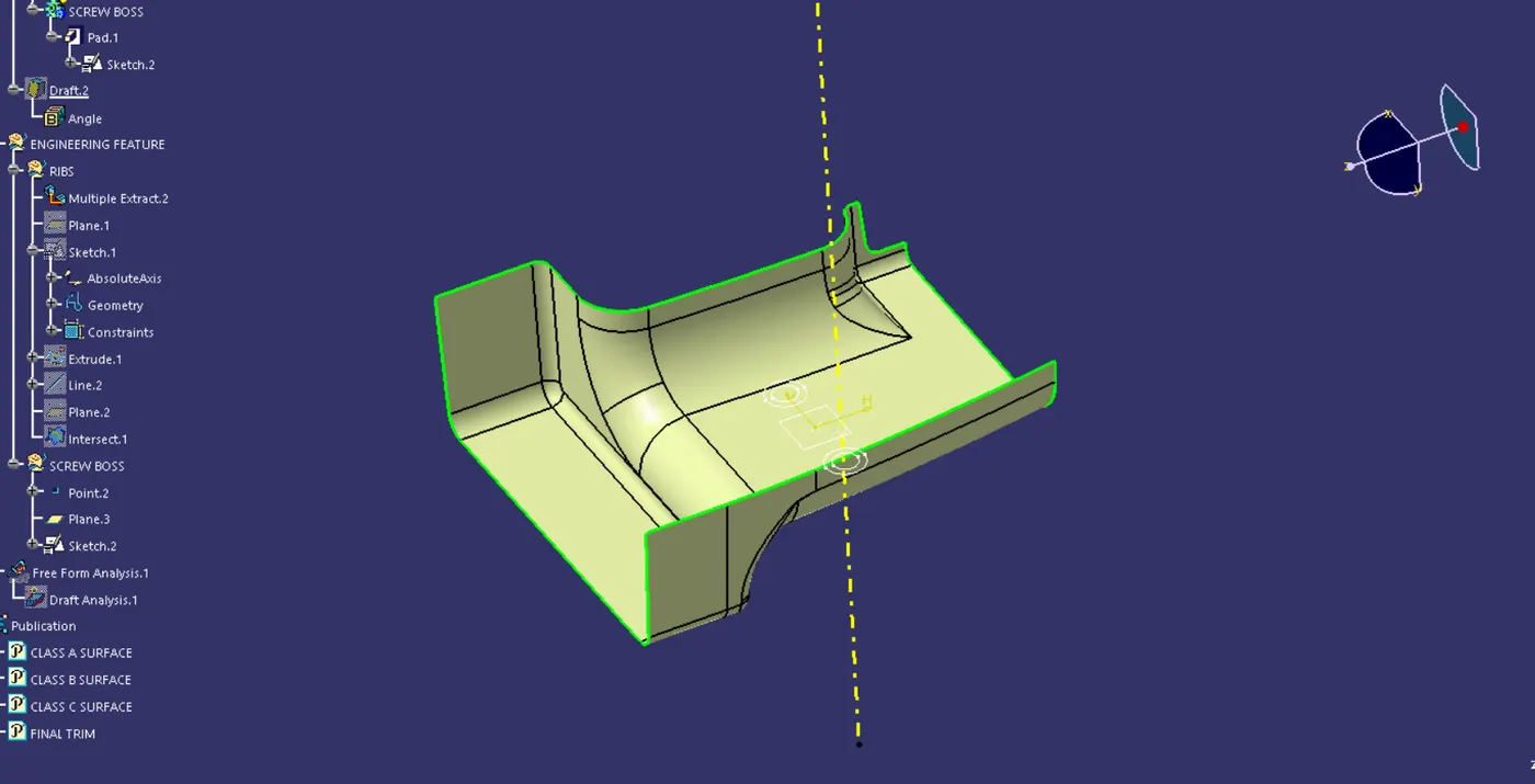
Class A Surface
Checking the connectivity by using the boundary or the intersection feature.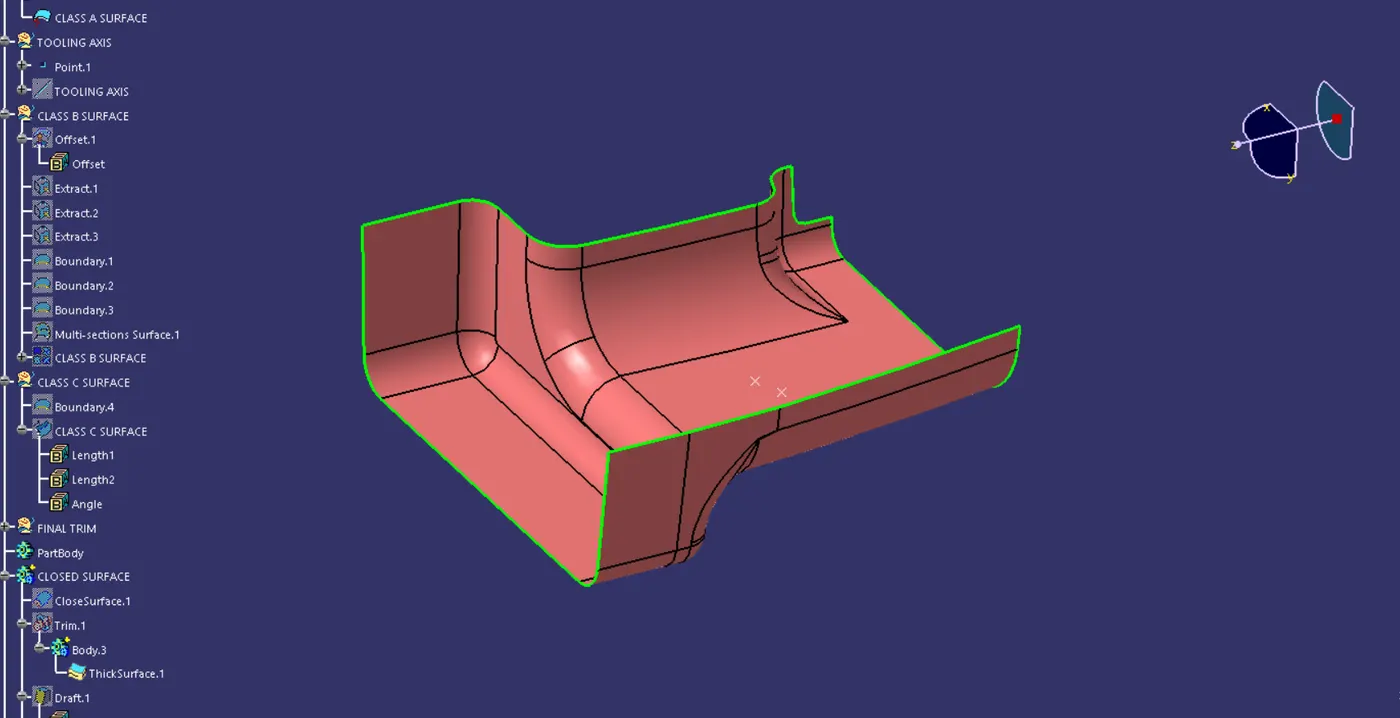
Class B Surface
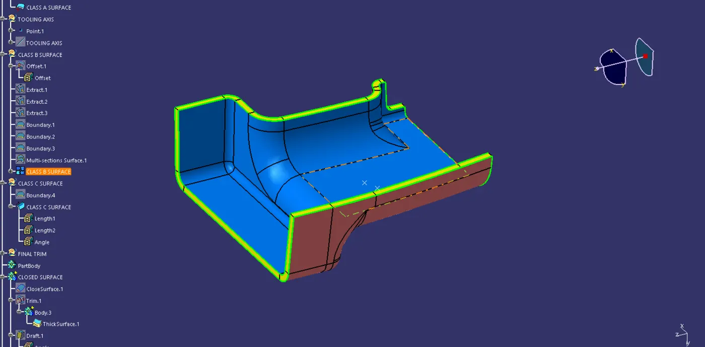
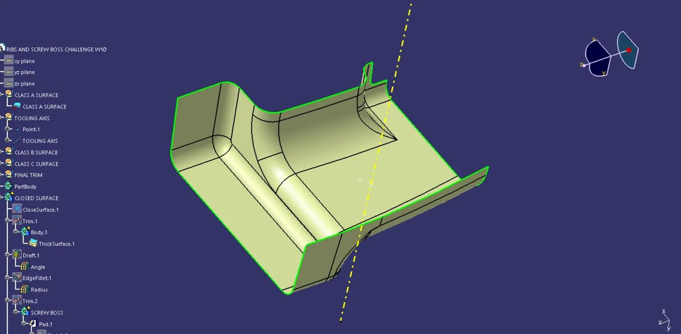
Created by extracing the walls, bezel and the base, untrimming it, extrapolating and offsetting it the given thickness before triming it all together.
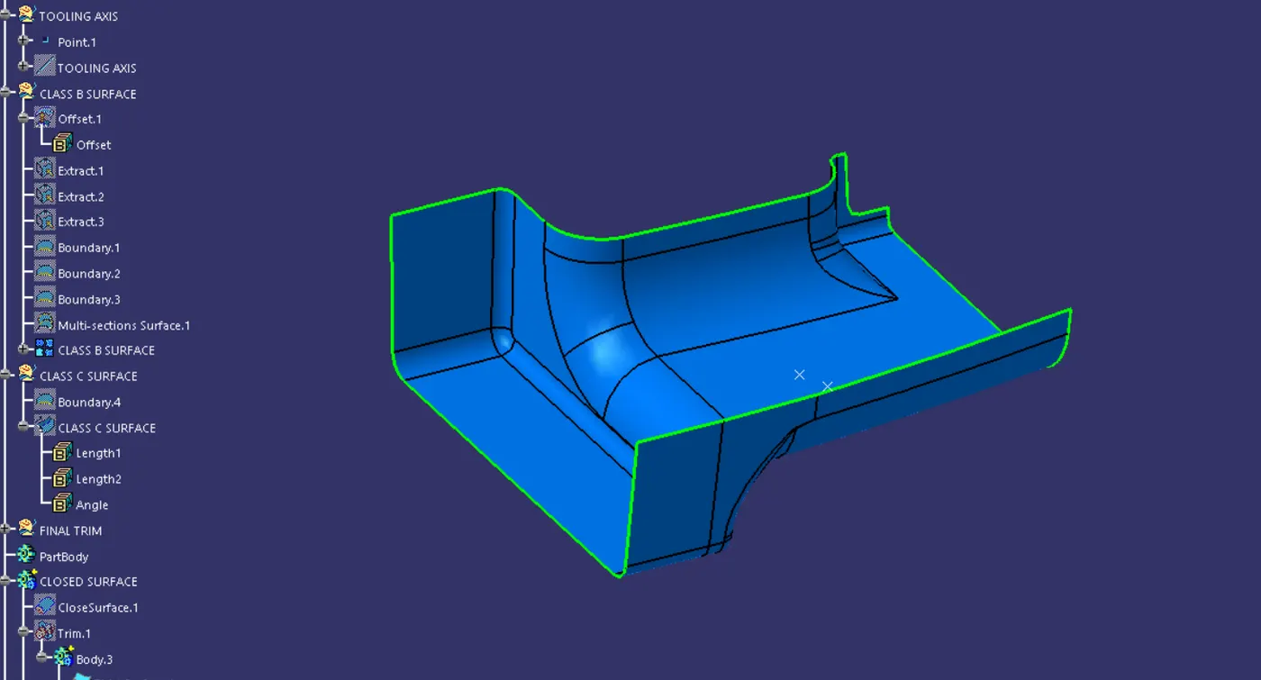
Class C surface
Created by sweeping the draft by direction method, where with the boundary of the class a surface is used as the guide curve along with the tooling axis we are able to join the class A & B surface together.
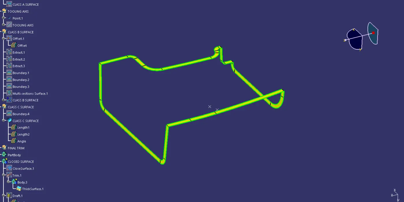
Step 1
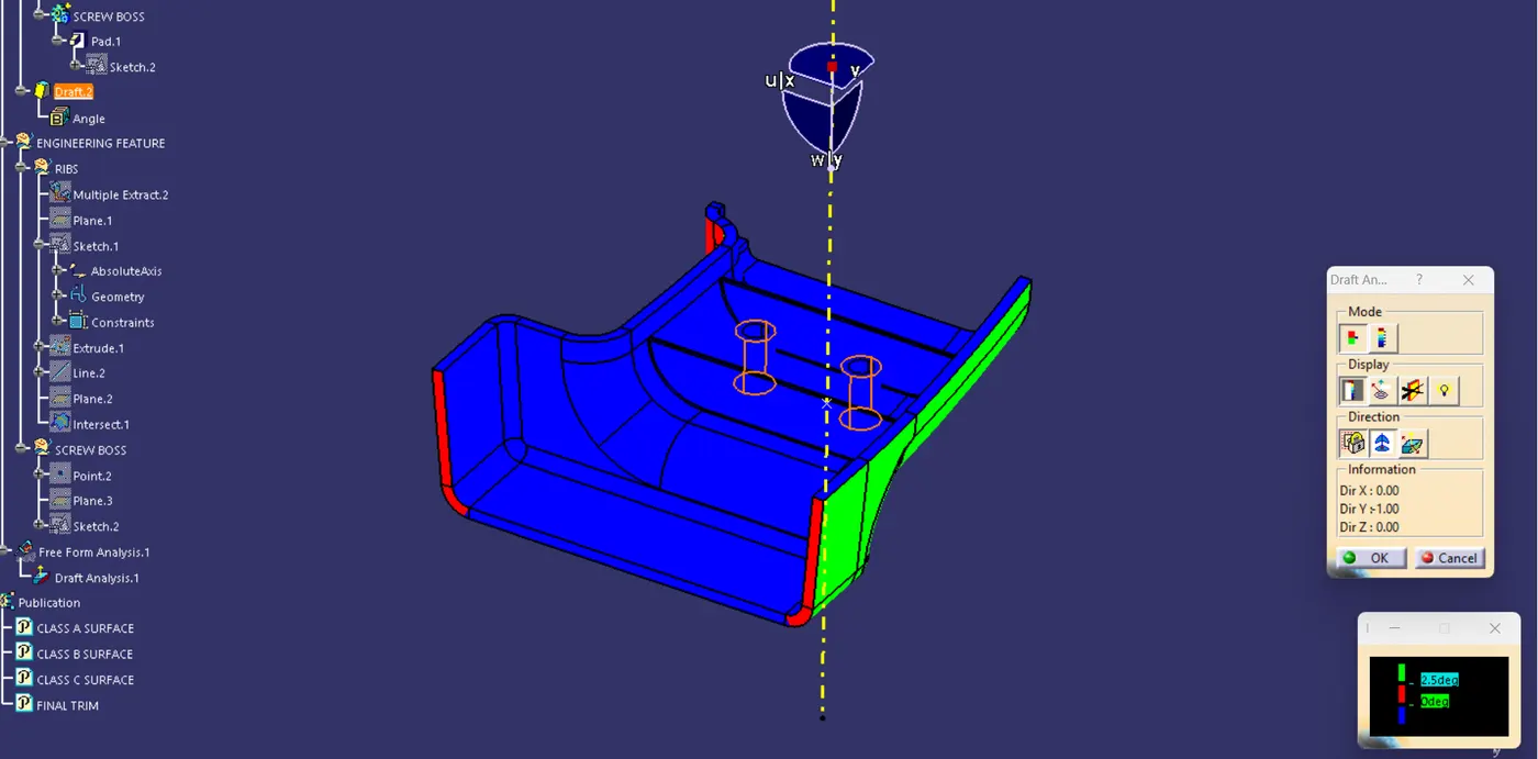
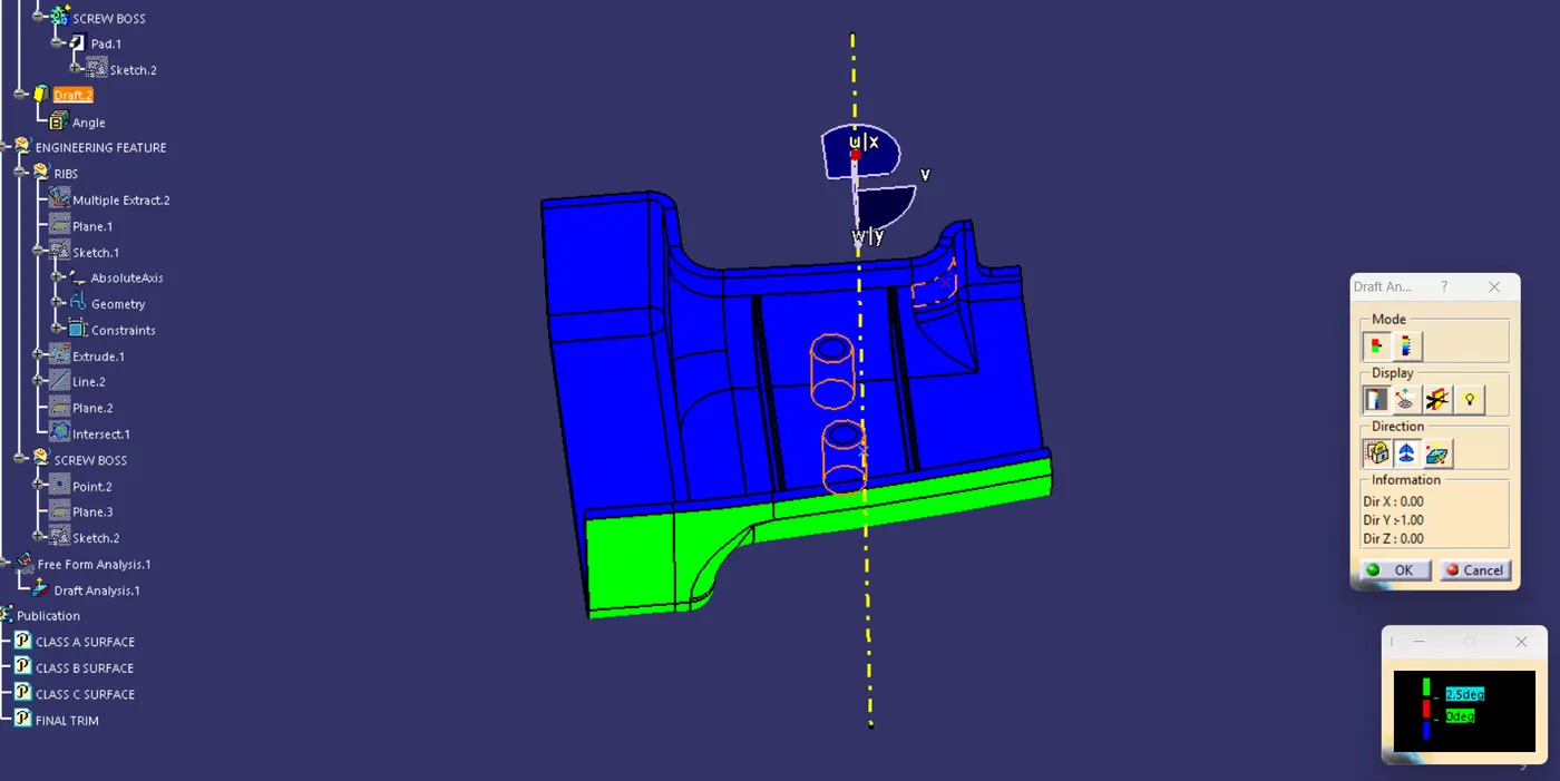
We checked through different positions where the part would be able to draft with the minimum draft angle and created a point and created a line and cross verified it with draft analysis and we found it out to the right axis and renamed the lline as the axis as the tooling axis.
Step 2
We started to extract, extrapolate and trim the surfaces of the door handle which was supposed to be the fillet and we used the multi section command to form the fillet. Now we offset the surface by 2.5mm to thicken it and then we joined it all together to get the Class B surface.
Step 3
To create the class C surface we at first created the boundary on the class A surface and then used the sweep method where the boundaries and tooling axis where chosen and a draft of 3 degree was given. Then we trimmed the class A & B together to form the Class C surface. Then we were able to get a closed surface.
Step 4
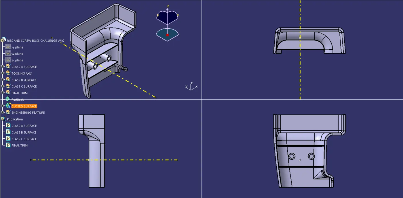
We then took the final trim to the product workbench and used the closed surface to thicken the Class C surface and then did the draft analysis, we dragged the compass fixed it to the tooling axis and then checked for any undercuts by giving it a 2.5 degree draft angle and we achieved an all green surface thus completing the challenge
Step 5
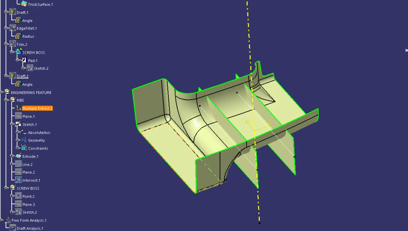
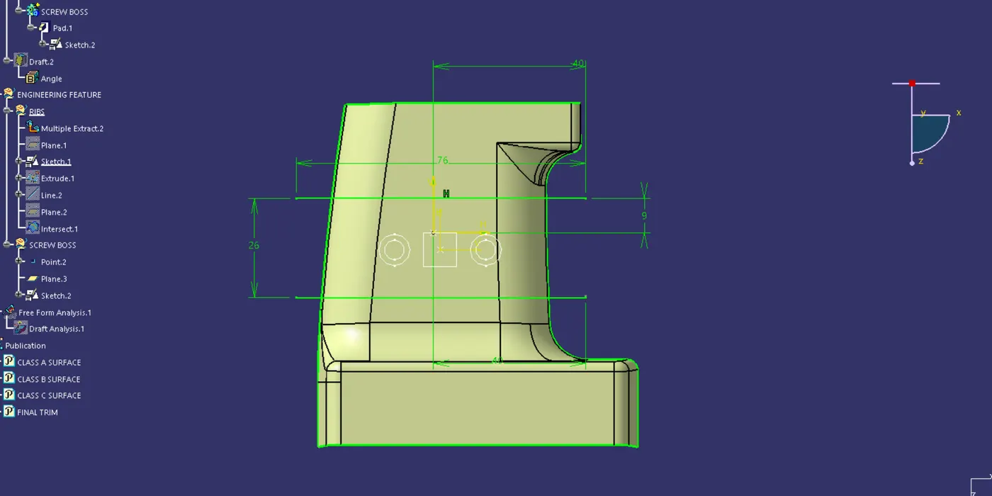
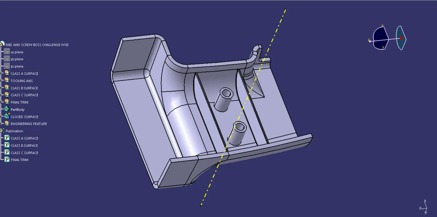
In this step we created the ribs for the door handle giving it the appropritate height and thickeness of 1mm using the thick surface command and also gave it the draft angle of 0.5 deg and completed it by giving it a edge fillet of 0.25 and trimed it with our final trim.
Step 6
Here we concluded the by creating the screw boss of two different dia, 8.2 and 5.2 and thickened it using the pad function on the sketch and later trimed it with the final trim we did give this a draft angle of 0.5 deg too.