Week 9 - Challenge 3 - Bumper
AIM: To create the half part of the car bumper by using direct offset method. through the given Class-A surface. To begin with, the tooling axis for the given Class-A Surface should be created meeting the requirements of the draft angle and at the end perform the Draft analysis on the model.
OBJECTIVE: To perform direct offset method unlike previous methods in challenges by first selecting the surfaces one by one. In this method we select the entire surface and offset it. Then we are left with some open parts from the previous filleted parts, surfaces, etc. which are not offsetted in CLASS B SURFACE are then extrapolated, joined, removed and trimmed. Then we create the CLASS C SURFACE by drafting the CLASS A SURFACE and then CLASS B and C SURFACES are trimmed to get a solid part saved as .CATPart
DESCRIPTIONS:
Tooling Axis: It is the line drawn out which is the direction in which the mold or core and cavity opens is the tooling axis.
Class A: It is the surface that is created by the concept sketches made by free hand sketchers. The finalised sketch is then fed to the computer and a 2D surface is created out of it by the use of a software like Alias. This computerized design is known as CLASS A SURFACE.
Class B: It is a reference surface that is created by the design engineer and is a copy of the CLASS A SURFACE that is at a distance equal to the thickness of the part (e.g. 3mm thickness).
Class C: It is again a reference surface that is created by the design engineer to connect CLASS A and CLASS B surface also known as the side wall or draft of the surface.
PROCEDURE:
Tooling Axis:
1) Download the .CATPart from the link given in the challenge. Open the .CATPart.
2) Select Start-> Shapes-> Generative Shape Design.
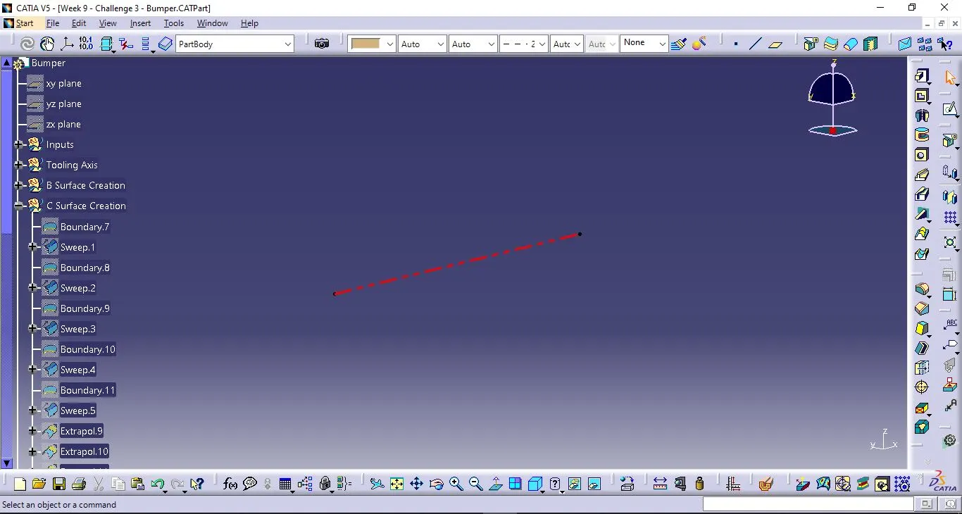
3) Create a point 'On Curve' on the edge of CLASS A SURFACE.
4) Through the point create a line along the X-axis. This will be the tooling axis and is named 'actual tooling axis'.
CLASS B SURFACE:
1) The CLASS A SURFACE was offsetted till 3mm.
2) The surfaces which were not intersecting were extracted and extrapolated.
3) Unnessesary parts were removed through join and split commands.
4) The fillet radius was obtained through circles drawn in it. Radius for CLASS B SURFACE was obtained as fillet radius-thickness.
5) When the exact copy of CLASS A SURFACE was created in CLASS B SURFACE then the entire CLASS B SURFACE was extrapolated one by one.
CLASS C SURFACE:
1) The boundary was created where we want to get the draft at 3 degrees from CLASS A SURFACE.
2) Then from that boundary drafting and extrapolation was made.
3) All the extrapolated and draftings were trimmed to get the extended surfaces.
4) Then the extended surface was joined with the CLASS A SURFACE to get the CLASS C SURFACE.
5) Any additional parts were removed to get actual CLASS C SURFACE.
Final trimming:
1) CLASS C and B SURFACE was selected and an intersection was made between the two.
2) If any black dots appear, then extensions in both the surfaces were checked.
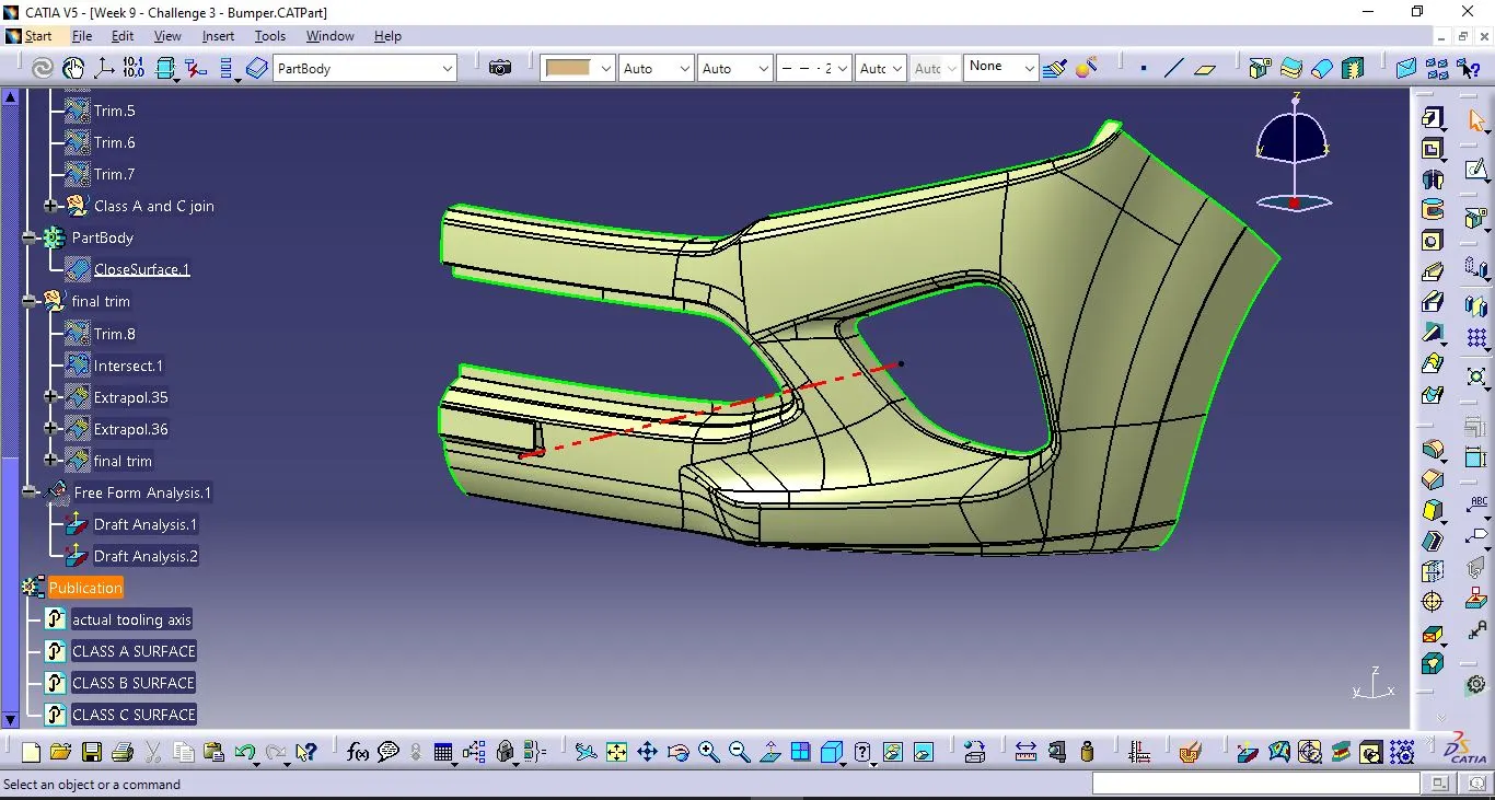
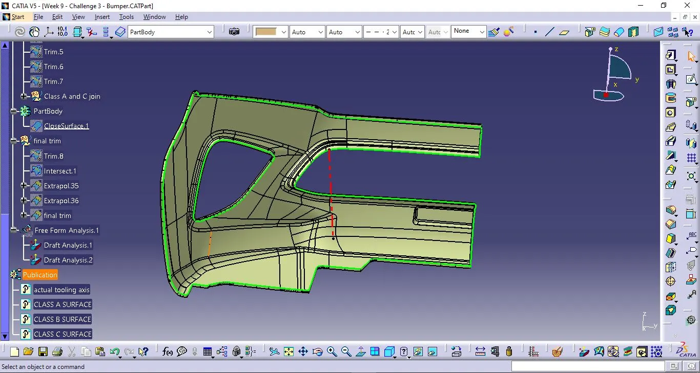
3) After achieving total intersection between both the surfaces, both were trimmed to get a closed surface.
4) That closed surface is made a solid part with 'Closed Surface' command.
Draft Analysis:
1) In plastic design, the draft analysis or angle that is considered in the OEMs is 3 degree.
2) First thing to carry out was to select the compass and set it on the tooling axis in upward direction.
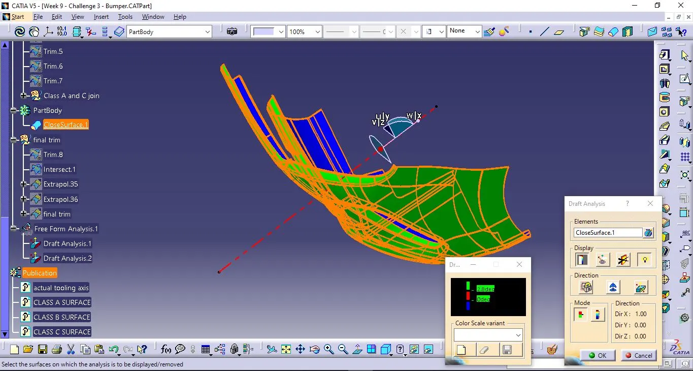
3) By clicking on the surface, the whole part turned into green color. If blue was visible that meant that the analysis was inversely done so just by flipping the direction, draft analysis.
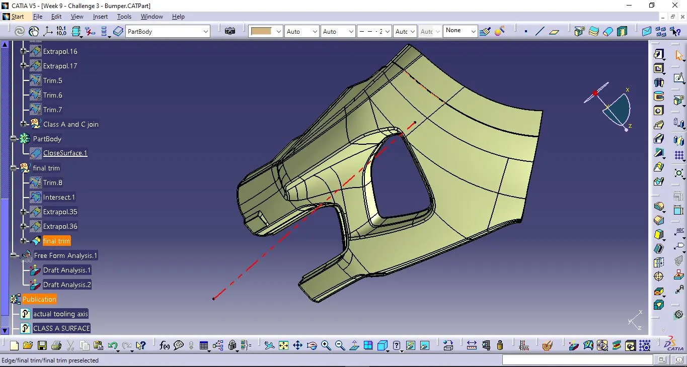
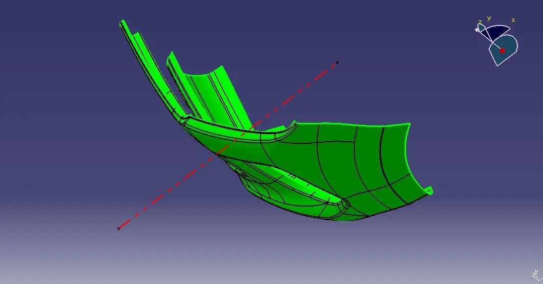
4) The hollow part was later created into a solid body by going the part body option and then selecting close body surface. *) Draft analysis on the solid part resulted in green, blue regions.
5) The green region shows the part which is toolable or produceable by the molding machine and the draft angle is 3degree.
6) Blue color region states that the part can be allowed in some OEMs but still need to be improved for the other OEMs as the draft angle is more than 3 degrees.
7) Red color which is not there in this case states that the draft angle is less than 3 degree and cannot be produced or if produced would be faulty.
8) The draft angle in draft analysis is given 2.8 to 3 degrees. The outcome came as fully drafted and is very toolable
OUTPUTS:
The outputs are given below in the form of screenshots of .CATPart as instructed above in the question for the completed model from this given challenge:
.CATPart:
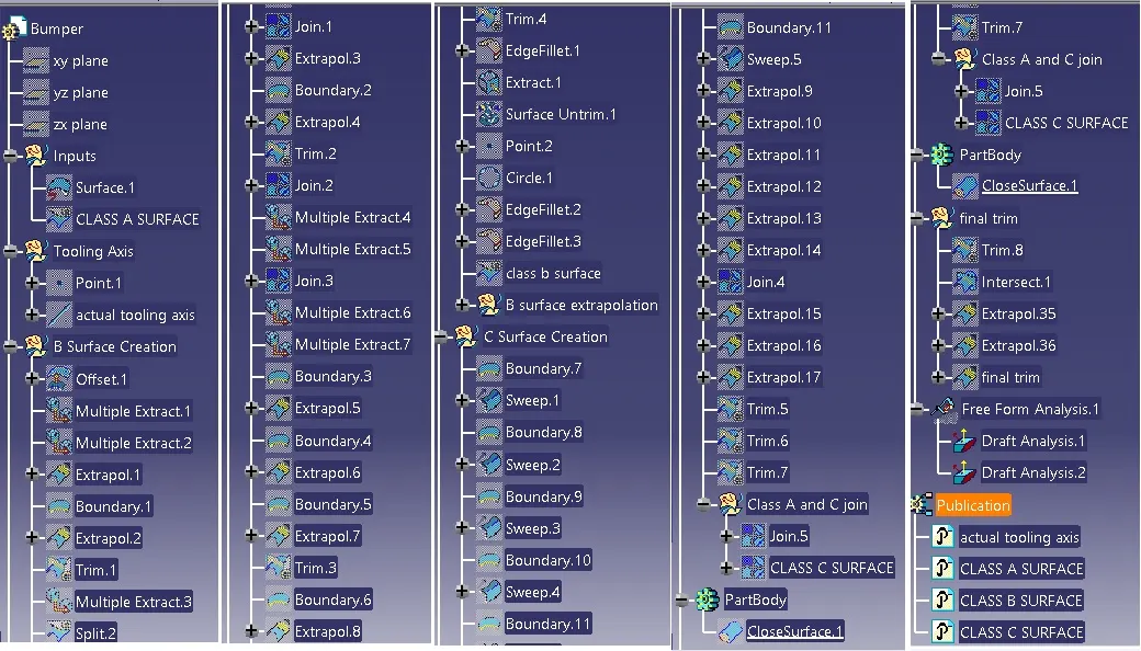
1) Tree Structure:
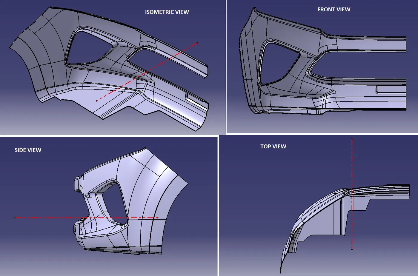
2) 3D Views:
INFERENCE:
The Part Design was done considering the standard procedures. Then it's .CATPart was obtained. The part was given below as a single .zip folder.