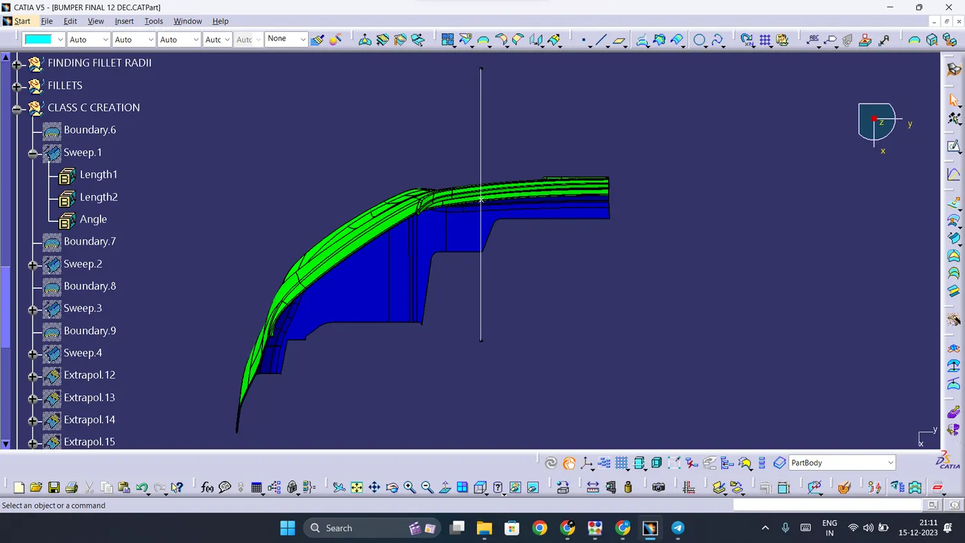
Week 9 - Challenge 3 - Bumper
CREATION OF TOOLING AXIS:
1. Before creating the tooling axis, we need to check the continuity of the provided Class A Surface by using boundary tool.
2. Then to create tooling axis, we first need to find out tooling direction. This can be done by analyzing in all three directions.
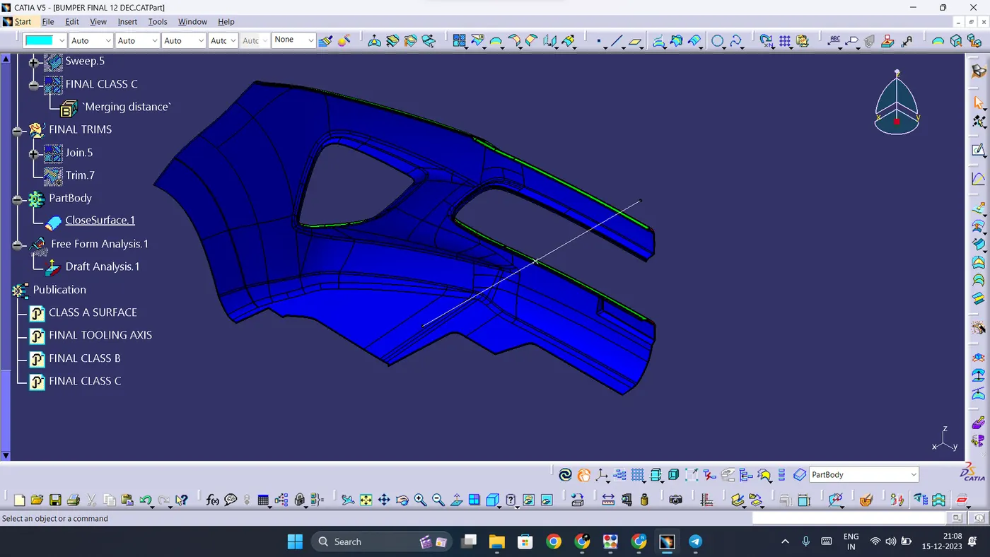
3. In this case, we can see that the x-direction is the tooling direction. To verify, we need to create a dummy tooling axis,
4. To create a dummy tooling axis, we need to create a point on any curve on the class A. Then we need to create a line in passing through the point in x direction.
5. On conducting draft analysis, we can see that all sides of the class A surface can be cleared by the dummy tooling axis. So this can be used as final tooling axis.
DRAFT ANALYSIS ON THE CLASS A SURFACE:
1. Insert a new draft analysis and click on the compass icon. Align the compass with the tooling axis and lock it.
2. Now click on the class A surface. The class A will change colours according to the colour scale variant.
3. We need a minimum draft angle of 3 degrees. Even if some faces only have 2.9, it is acceptable. To check this, we can analyse under running point to find out the angle at specific points.
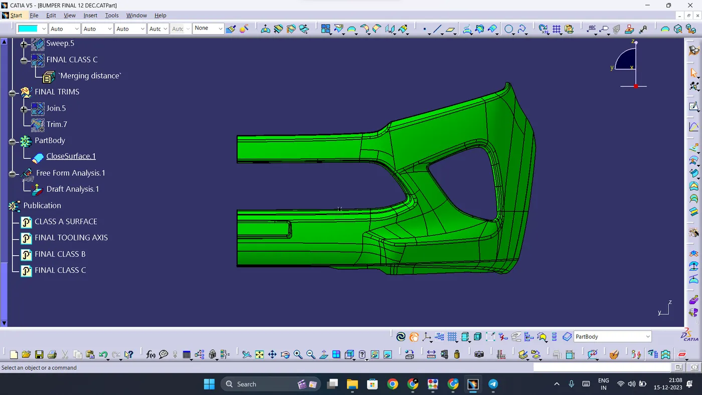
4. For an angle below 0 degrees, the colour is blue. For an angle between 0 and 3 degrees, the colour is red. For any angle over 3 degrees, the colour is green.
5. So ideally we want our class A to be completely green. 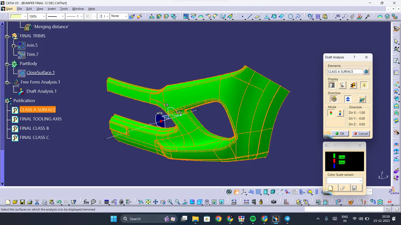
DRAFT ANALYSIS ON THE PLASTIC COMPONENT:
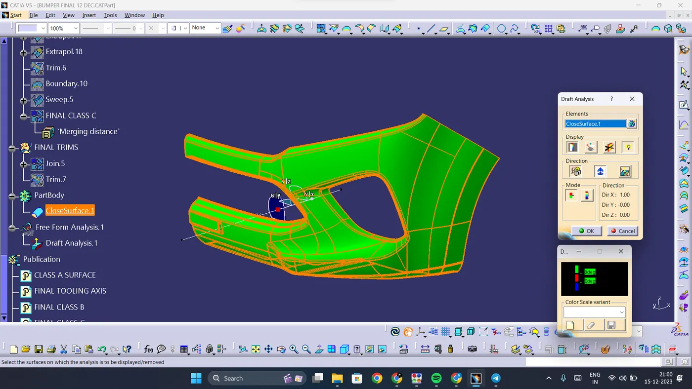
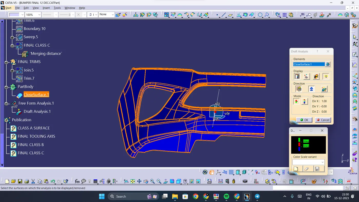
SCREENSHOTS OF PART BODY IN VARIOUS ORIENTATIONS:
1. ISOMETRIC VIEW:
2. FRONT VIEW:
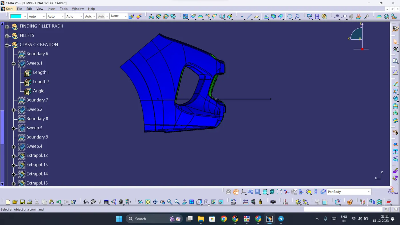
3. SIDE VIEW:
4. TOP VIEW: