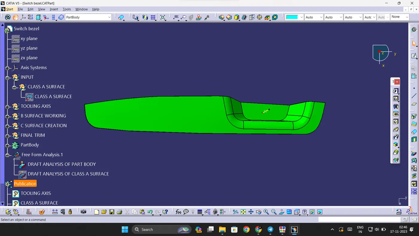
Week 9 - Challenge 2 - Switch Bezel Design
CREATION OF TOOLING AXIS:
1. Upon visual inspection, the conclusion has been made that the Z - direction is the most ideal tooling direction.
2. Sketcher method can be used to construct the tooling axis.
3. Firstly, an axis system is required on the surface and to construct an axis system, a point is required. Create a point on the centre of the base surface.
4. Create an axis system at this point with the same orientation as the absolute axis system.
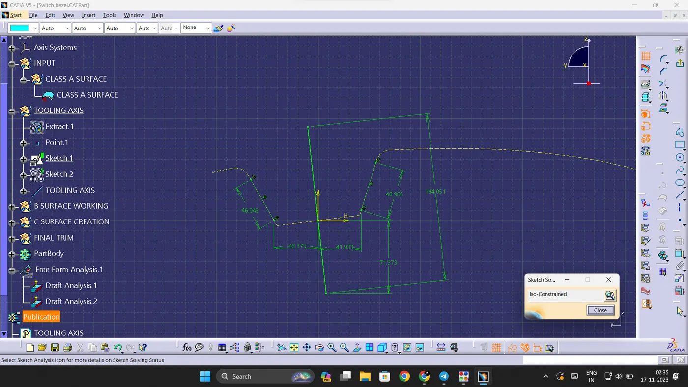
5. Now create a positioned sketch on the YZ plane with the point as reference.
6. Create a projection of the surface by using "Project 3D elements" tool. Make this projection a construction element.
7. Create two lines coinciding with but extending beyond the limits of the outer two lines which are projections of two of the outer walls of the surface. Make these two lines construction elements as well.
8. Construct a line bisecting these two lines before making them construction elements. Make sure the sketch is iso-constrained. Then exit the workbench.
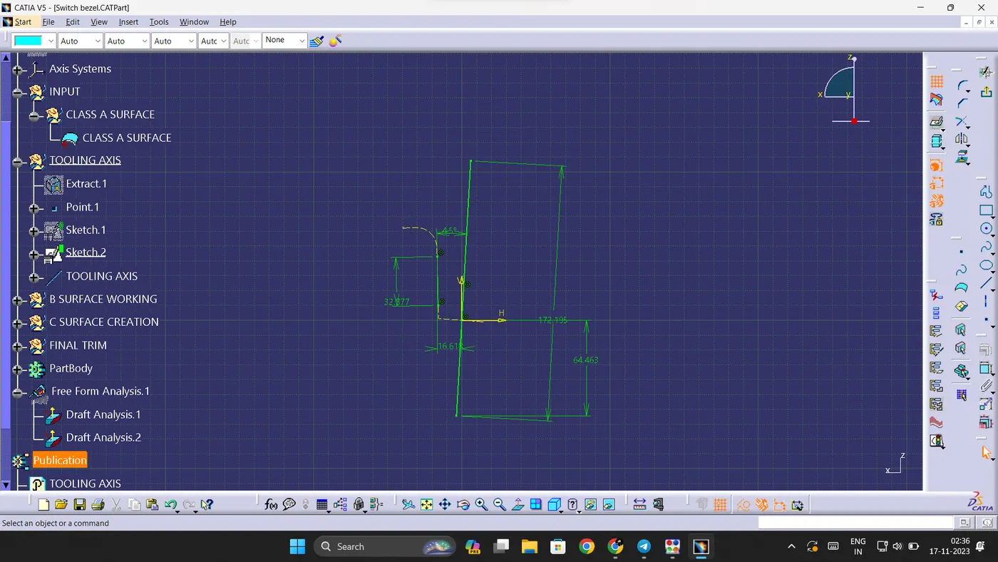
9. Now create another positioned sketch, this time in the XZ plane. Repeat the process of projecting the surface and making the projection a construction element.
10. In this case there is only one outer line. So we can simply create a line coinciding with that one line and constrain it.
11. Now we can create another line passing through the origin of the XZ plane and constraint it in such a way that it is at about 3 degrees with the outer wall. We chose 3 degrees because it is the desired draft angle. This angle can be changed later on.
12. Make the first line a construction element. Exit work bench after making making sure the sketch is iso-constrained.
13. Now create a line bisecting these two sketch lines passing through the origin point of the created axis system. This line will be our tooling axis.
DRAFT ANALYSIS OF THE PART BODY:
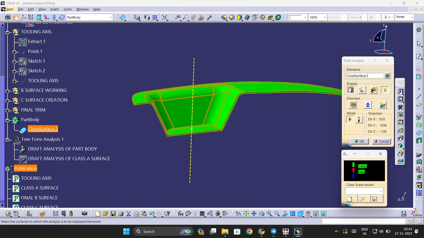
1. As soon as the part body has been created using the close surface tool in the part workbench, we can now do a draft analysis of the part body.
2. Insert a new draft analysis. Click on the compass icon and align it with the tooling axis. Then with the x mark, click on the part body.
3. The part body attains colours according to the angle at which the surfaces are aligned to the tooling axis. These colours can be assigned in the colour variant scale.
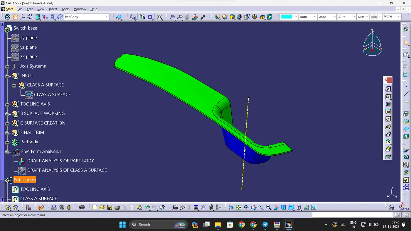
4. In this draft analysis, the colour green has been assigned to the surfaces which are at an angle greater than 3 degrees. Red has been assigned for surfaces which are at an angle between 0 and 3 degrees. Colour blue has been assigned to surfaces which are at an angles less than zero degrees.
5. As you can see, some surfaces are not being cleared as they do not have required 3 degrees draft. This is due to the line in sketch 2 as there was only one wall for us to work with.
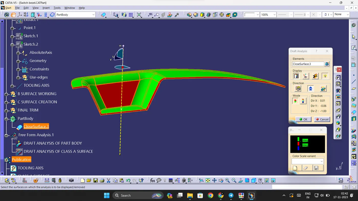
6. This can be corrected by changing inclination angle of this line in the second positioned sketch. We need to use trail and error by changing the inclination to 3.5, 4, etc.
7. By trail and error we can see that the surface can be cleared when the inclination in the sketch has been changed to 4.5 degrees.
8. Still, on some surfaces, we can still see red patches. By using "analyse under running point" tool, we can see that the angles are very close to 3 degrees, like 2.987, 2.991, etc.
9. So we can change the upper limit to 2.9 instead of 3. Now when we do draft analysis, we can see that the analysis is successful and the whole top surface of the part body is green in colour.
DRAFT ANALYSIS OF THE CLASS A SURFACE:
1. Insert a new draft analysis and click on the compass symbol. Make sure everything except the Class A Surface are hidden.
2. Now align the compass with the tooling axis and click on the class a surface with the x symbol.
3. We can immediately see that the whole class A surface has instantly turned green with the upper limit of 2.9 degrees.
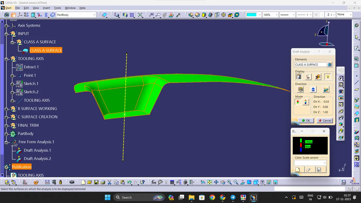
4. So this means that all the faces of the class A can easily be cleared with respect to the created tooling axis.
IMAGES OF DRAFT ANALYSIS OF CLASS A SURFACE WITH COLOUR SCALE VARIANT:
IMAGES OF DRAFT ANALYSIS OF PART BODY WITH COLOUR SCALE VARIANT:
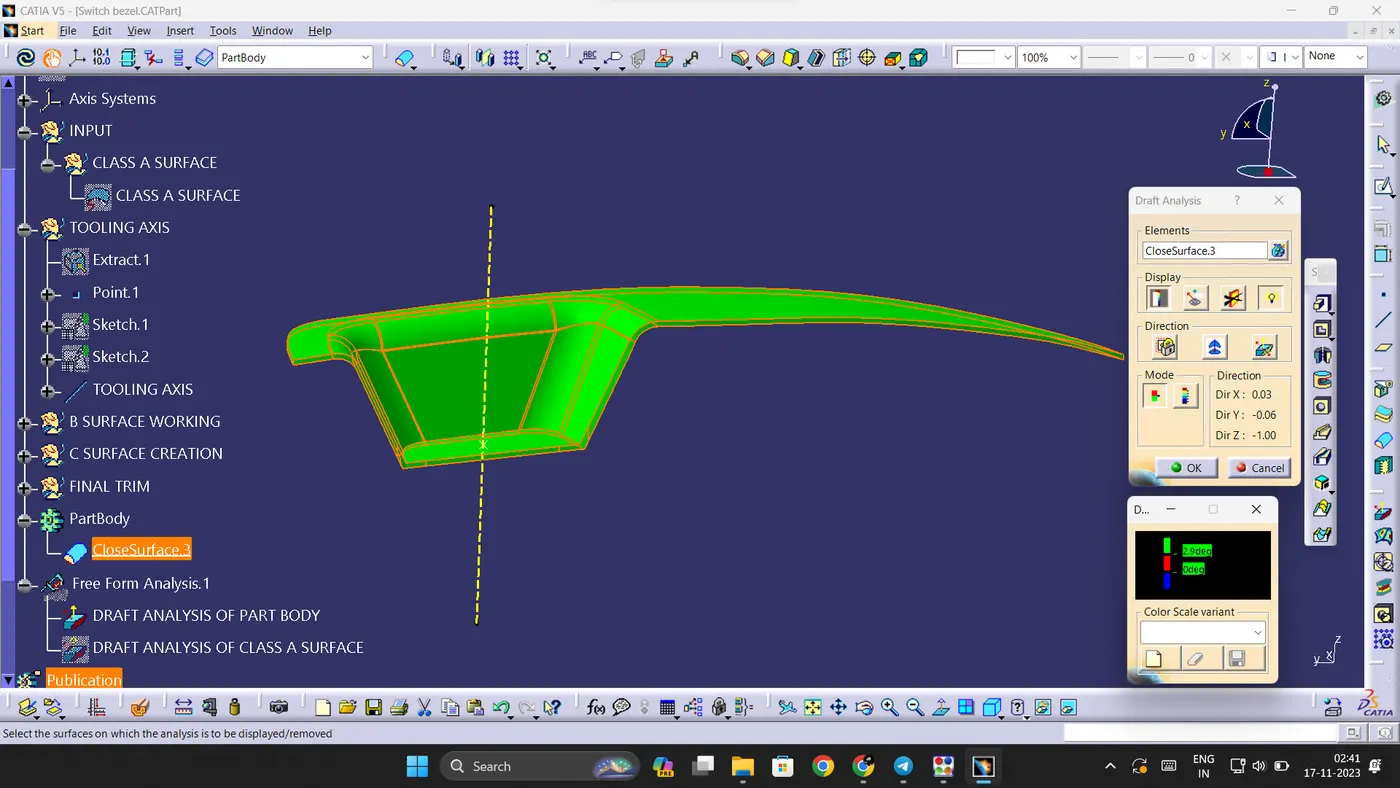
IMAGES OF THE PART BODY WITH DRAFT ANALYSIS COLOURS IN VARIOUS ORIENTATIONS:
ISOMETRIC VIEW:
FRONT VIEW:
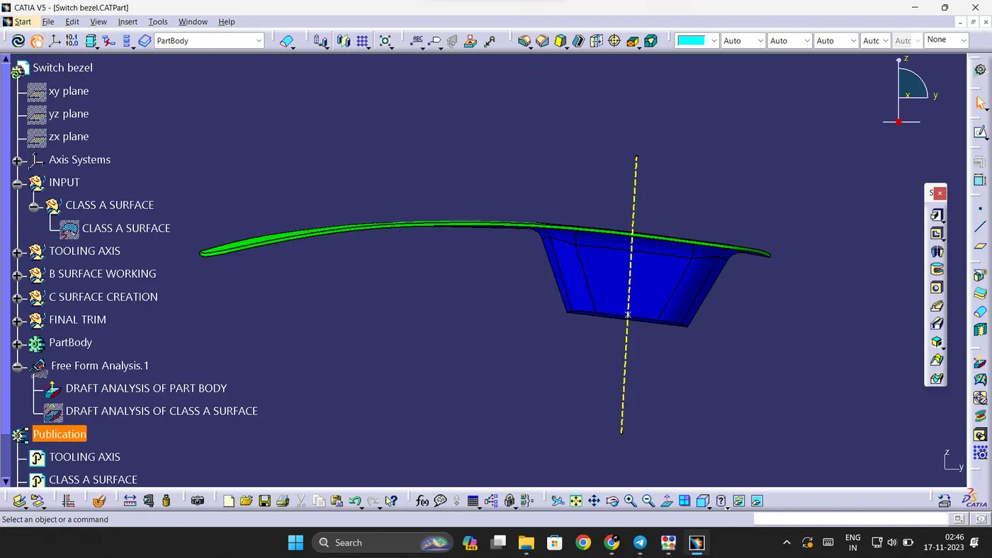
BACK VIEW:
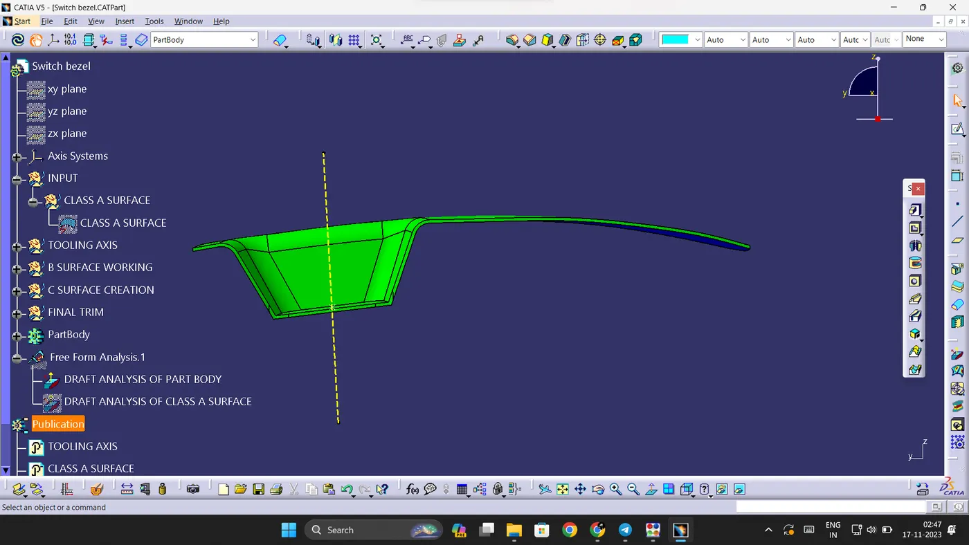
SIDE VIEW:
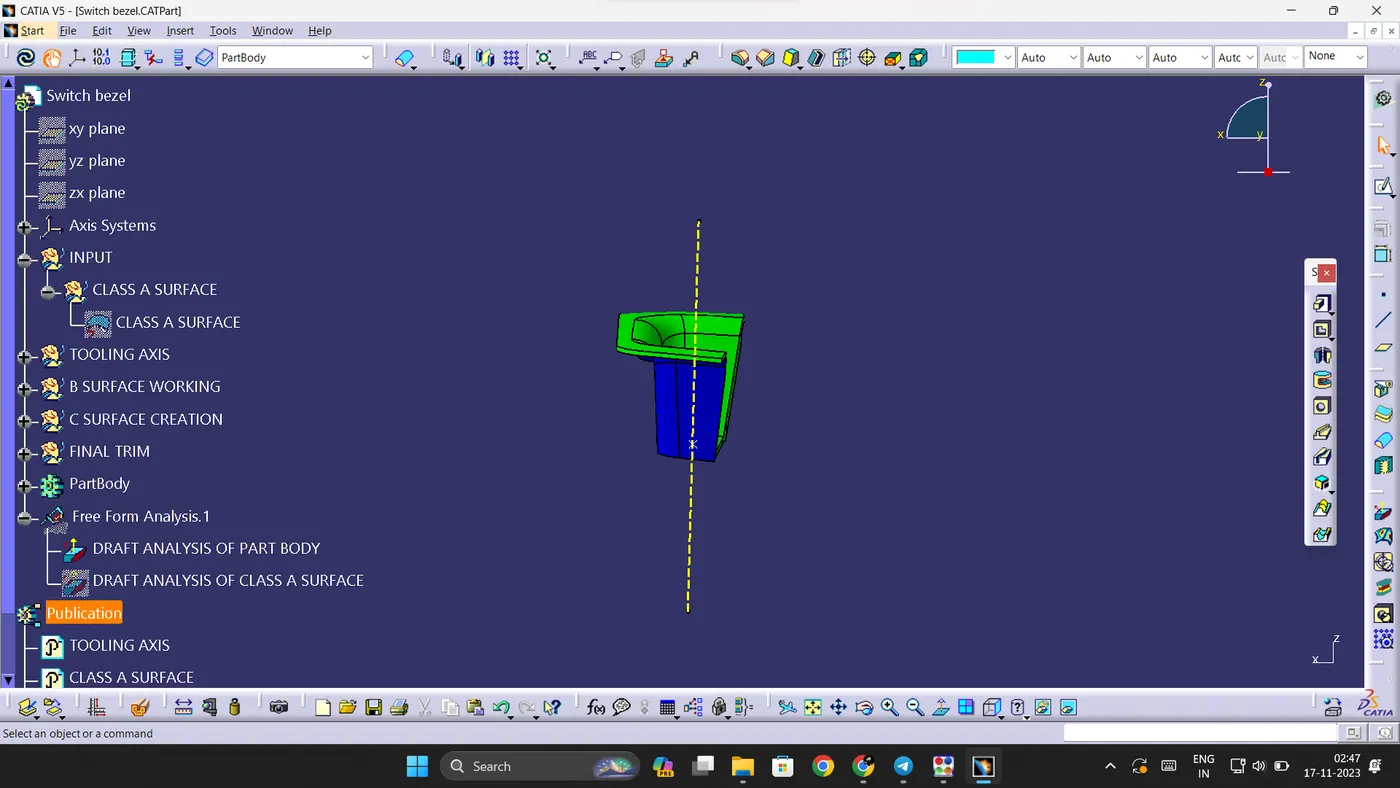
TOP VIEW: