Week 9 - Challenge 3 - Bumper
Create the Bumper Plastic component through the given Class-A surface. To begin with, the tooling axis for the given Class-A Surface should be created meeting the requirements of the draft angle and at the end perform the Draft analysis on the model.
Thickness of Plastic Part - 3 mm
Step 1:- First open Given CAT file in catia.
Step 2:- check draft analysis and boundry Continivity.
Step 3:- Now add tooling axis by Adding point plane and axis.
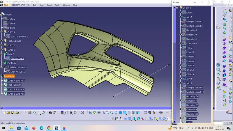
Step 4:- Now add class B surface, extract that surfaces then offset it by 3 mm .
Tooling Axis Creation
- Tooling axis here created is by selecting one of the natural axes as it clears the draft.
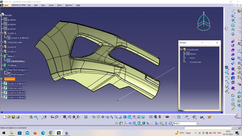
- Here, tooling axis is created by extracting one of the surfaces for creating a point and a new axis is created at that point.
- So, a flat face is extracted and created a point at its centre. Axis is also created at that point.
- Now, line is created using line tool and giving line type as point-direction and selected the point and direction for creating tooling axis and tooling axis is created along x direction.
Creation of Class B and Class C Surface
Class B
- To create the class B surface, offset the class A surface inside as per our thickness requirement (here the thickness is 3mm, so I offset the class A to 3mm inside).
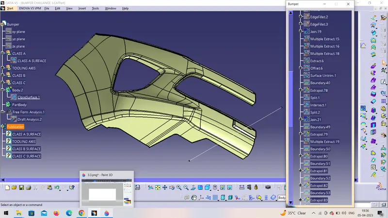
- Once the offset is created, we can observe some patches on the offset surface by taking the boundary for the offset surface, those patches are formed due to the fillets on the class A surface.
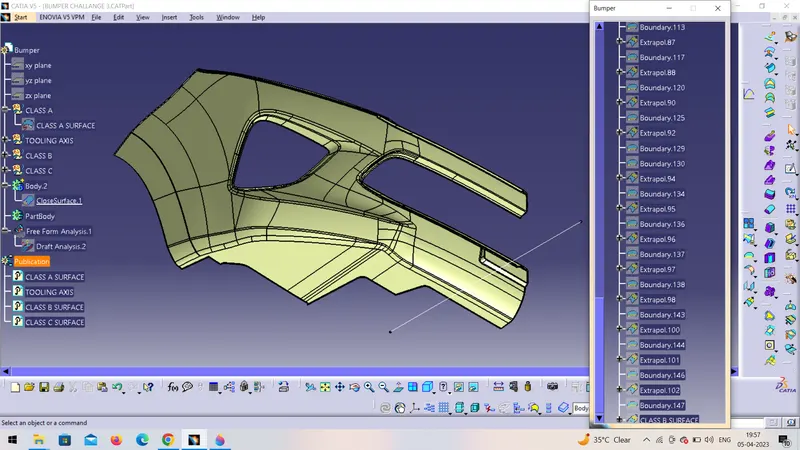
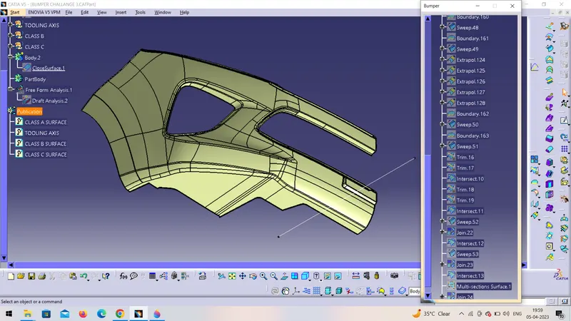
- We covered the patches by using the different surface commands (multi sections, extrapolate) in the Generative Shape Design workbench.
Class C
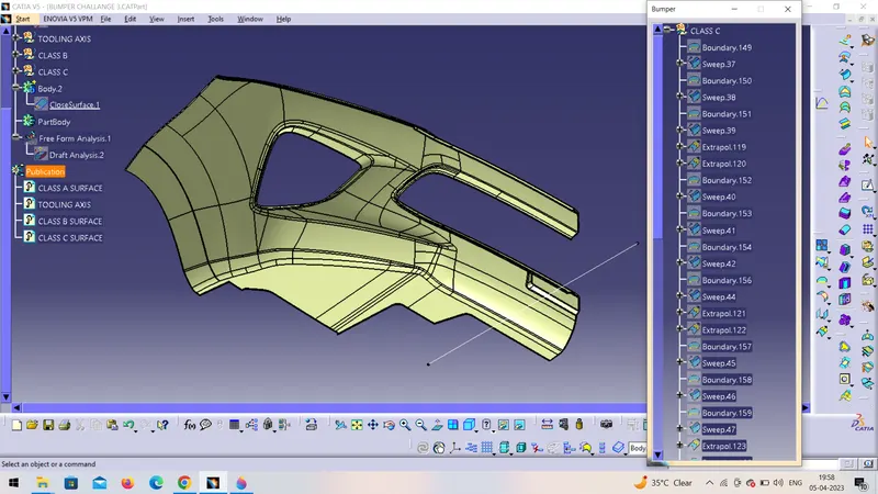
- To create the class C surface concerning the boundary of the class A surface, I used the sweep command. Initially, I extracted the boundary of the class A surface with tangent continuity, and I sweep the extracted boundary concerning the surface at 90deg (for draft angle) for 4mm to intersect properly with the class B surface.
- Once we sweep all the surface boundaries of class A, extrapolate the swept surfaces until both surfaces got intersected properly, and trim them to remove extended extrapolated surfaces to get a proper sweep boundary throughout the entire surface, including the centre hole of the bumper.
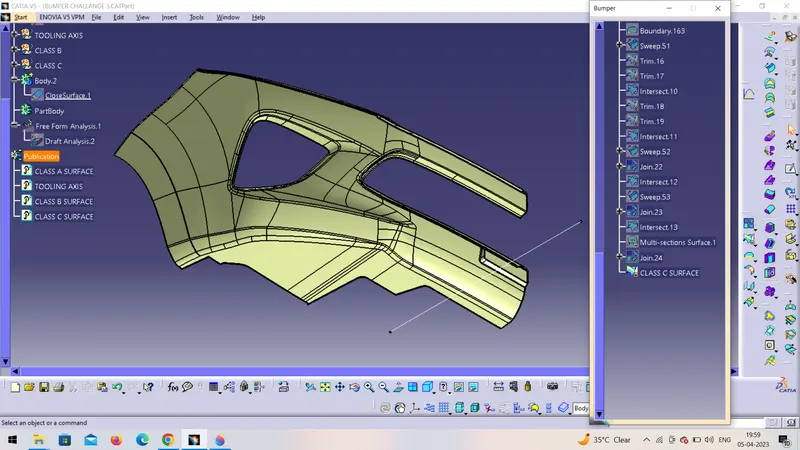
- Now, join both class A and sweep boundary to get the complete class C surface.
- Now Class A surface and Class C surface is joined.
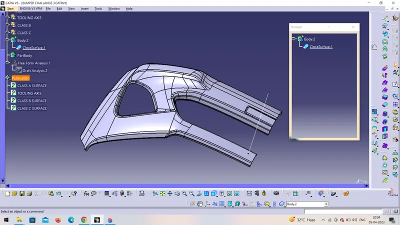
- Now Class B surface is also trimmed with the obtained surface to get the closed surface.
- Boundary check is done to check for any open boundaries in the part. The closed surface then obtained moved to part design and close surface tool is used to obtain the part
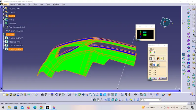
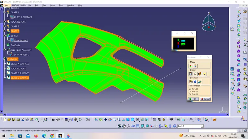
Draft Analysis:
- Go to the Insert menu and select the Analysis option.
- Select Feature Draft Analysis.
- Select the Material option and select the surface.
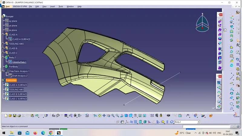
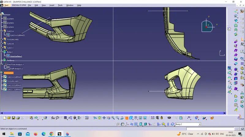
- Drag the compass and place it on the tooling axis.
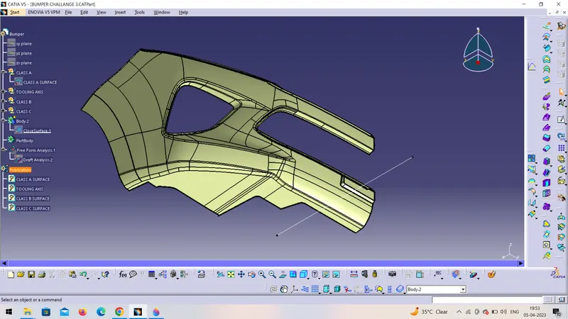
- Make sure that the top surface is in green color as the draft angle should not exceed 3deg.
- Click on Okay.
In this way challange is done.
THANK YOU.