Week 9 - Challenge 3 - Bumper
BUMPER DESIGN
OBJECTIVE:
Create the Bumper Plastic component through the given Class-A surface. To begin with, the tooling axis for the given Class-A Surface should be created meeting the requirements of the draft angle and at the end perform the Draft analysis on the model.
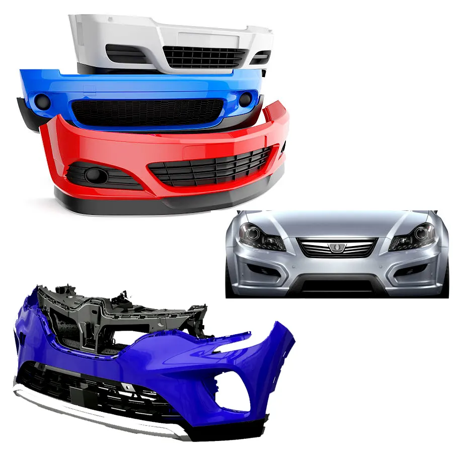
INTRODUCTION :
A bumper is a structure attached to or integrated with the front and rear ends of a motor vehicle, to absorb impact in a minor collision, ideally minimizing repair costs.[1] Stiff metal bumpers appeared on automobiles as early as 1904 that had a mainly ornamental function.[2] Numerous developments, improvements in materials and technologies, as well as greater focus on functionality for protecting vehicle components and improving safety have changed bumpers over the years. Bumpers ideally minimize height mismatches between vehicles and protect pedestrians from injury. Regulatory measures have been enacted to reduce vehicle repair costs and, more recently, impact on pedestrians.
Today, standard passenger vehicle bumpers have a rigid reinforcing bar under the outer cover, with sections of compressible foam or plastic underneath.
A bumper is made up of four parts:
• Bumper cover.
• The bumper absorber.
• The bumper reinforcement bar.
• The bumper mounting system.
Bumpers of most modern automobiles have been made of a combination of polycarbonate (PC) and acrylonitrile butadiene styrene (ABS) called PC/ABS.
Acrylonitrile Butadiene Styrene(ABS):
Acrylonitrile Butadiene Styrene is a copolymer made by polymerizing styrene and acrylonitrile in the presence of polybutadiene. The styrene gives the plastic a shiny, impervious surface. The butadiene, a rubbery substance, provides resilience even at low temperatures. A variety of modifications can be made to improve impact resistance, toughness, and heat resistance.
PROPERTIES OF ABS:
PROPERTY METRIC UNITS ENGLISH UNITS
General
Density 1.01e3 - 1.21e3 kg/m^3 63.1 - 75.5 lb/ft^3
Mechanical
Yield Strength 1.85e7 - 5.1e7 Pa 2.68 - 7.4 ksi
Tensile Strength 2.76e7 - 5.52e7 Pa 4 - 8.01 ksi
Elongation 0.015 - 1 % strain 1.5 - 100 % strain
Hardness (Vickers) 5.49e7 - 1.5e8 Pa 5.6 - 15.3 HV
Fracture Toughness 1.19e6 - 4.29e6 Pa/m^0.5 1.08 - 3.9 ksi/in^0.5
Young's Modulus 1.19e9 - 2.9e9 Pa 0.16 - 0.421 10^6 psi
DESIGN FLOW CHART:
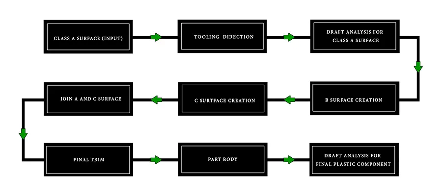
CLASS A SURFACE:
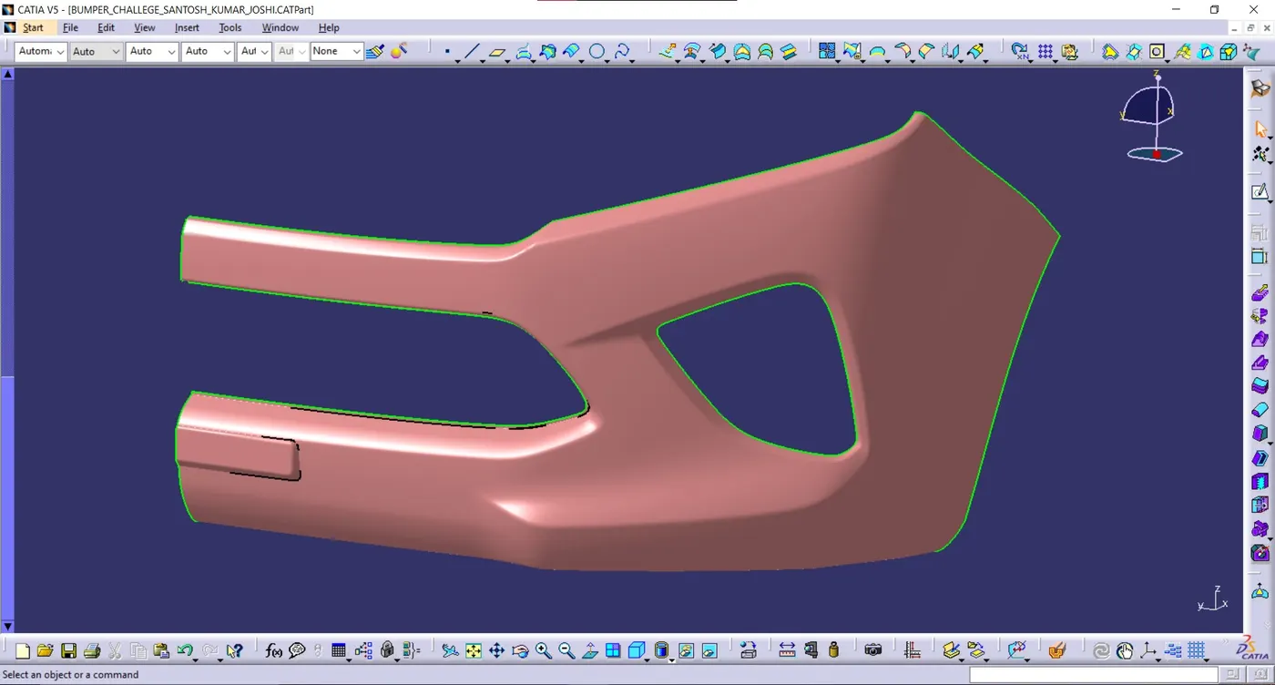
• In automotive design, a class A surface is any of a set of freeform surfaces of high efficiency and quality.
• It is the visible aesthetic surface of any automotive component.
• Class A surface refers to those surfaces which are visible and abide to the physical meaning, in a product.
• This classification is primarily used in the automotive and increasingly in consumer goods industry.
• It is a requirement where aesthetics has a significant contribution.
• For this reason, the exterior of automobiles is deemed Class-A.
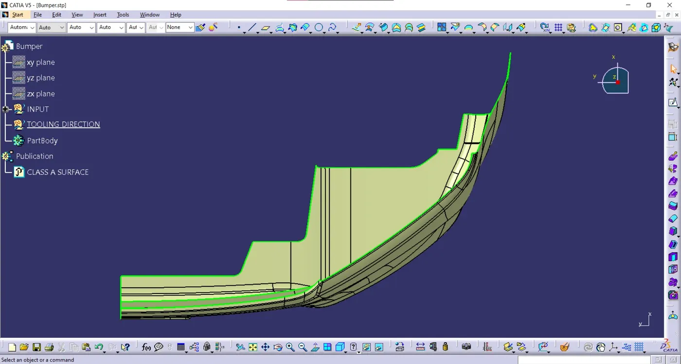
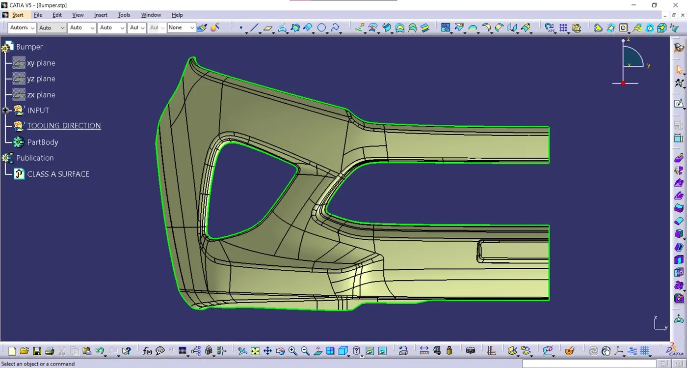
• Below is the CLASS SURFACE that is given to me as input.
CHECK ALL 3 AXIS Y,Z AND X TO DECIDE TO CREATE TOOLING AXIS.
Here we decided to make the tooling axis in the X direction, which is suitable for us.
TOOLING AXIS:
• Considering the Ejection from the cavity of the mould after manufacturing the interior trim must have the nominal degree draft angle.
• Hence the tooling axis is created by considering the above factor.
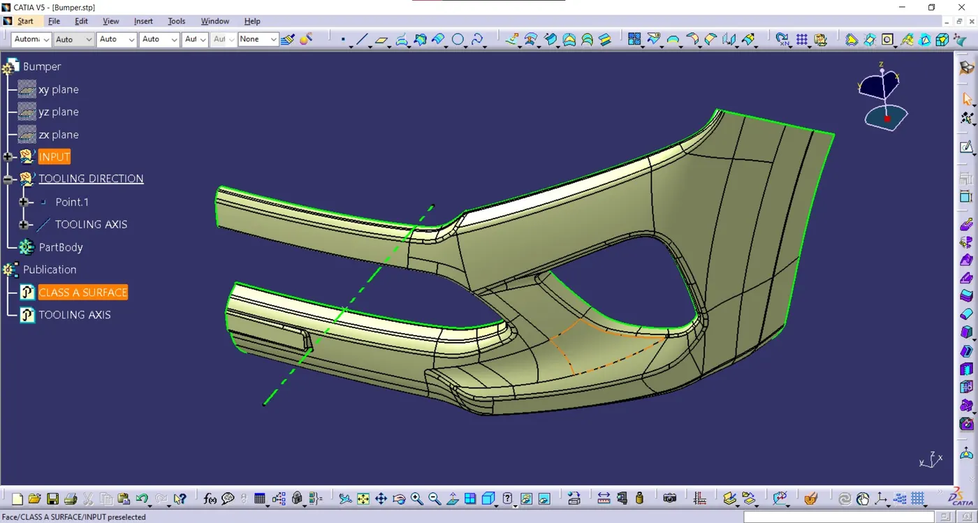
• The direction in which the mold or core and cavity opens is the tooling axis.
• In this case below is the tooling axis that I have used.
• The Green Dotted Line is our tooling axis.
DRAFT ANALYSIS FOR CLASS A SURFACE :
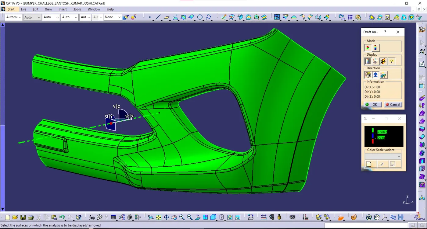
• The draft analysis technique is used to analyze whether our part model created is manufacturable based on the draft condition applied. To perform draft analysis the view parameters are set to material mode.
• Then insert the feature draft anlysis select the axis system and drag the axis system to align and coincide with the tooling axis and lock the orientation.
• This axis system defines the draft direction according to the tooling axis. Set the minimum value, here it is set to 3 degrees and it will be displayed in green colour. Now select the running point tool to measure the draft angle at various locations.
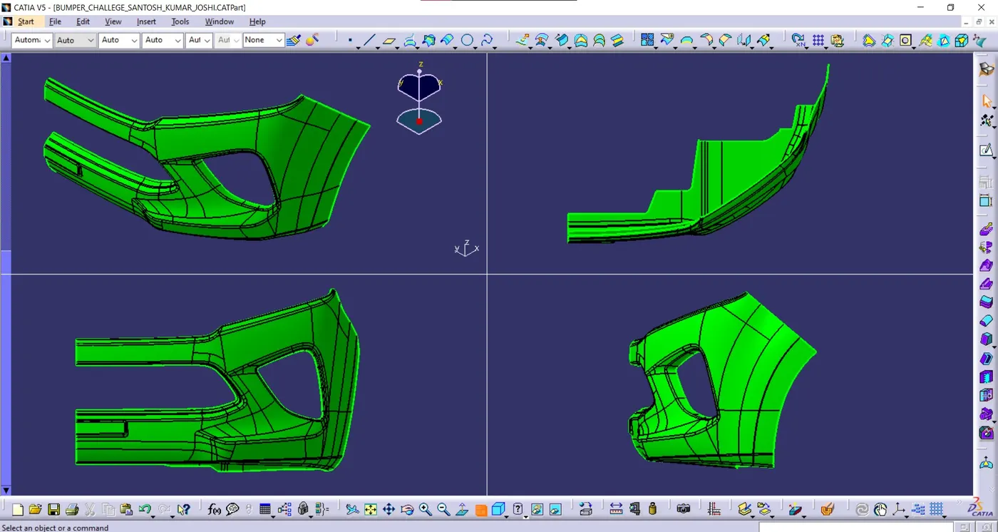
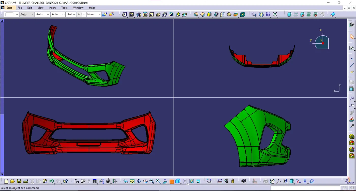
Here below on the image isometric, front, side and top/bottom view available.
B SURFACE CREATION:
• Class B surfaces are Engineering Surfaces which are invisible to the eyes or often on the back side of the Class A surfaces.
• It is mainly the thickness of the component or Class A.
• These surfaces need to be designed as per the Class A surface i.e., the continuity, thickness of the component, functionality etc should be maintained.
• These surfaces include the main engineering features such as Screw bosses, Ribs, Snaps, Stiffeners and fixations.
• B surfaces also do not contain any aesthetic styling content and textures since it is not visible to eyes.
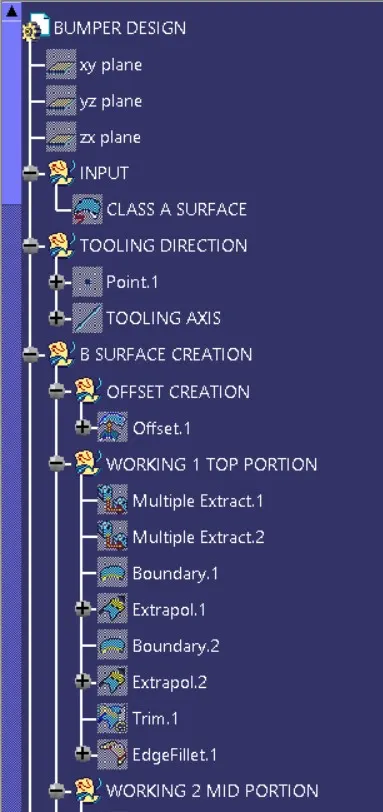
OFFSET CREATION:
here I have taken 3 mm offset of class a surface behind.
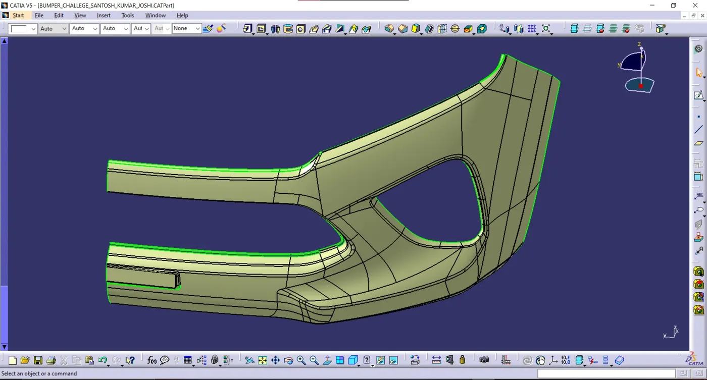
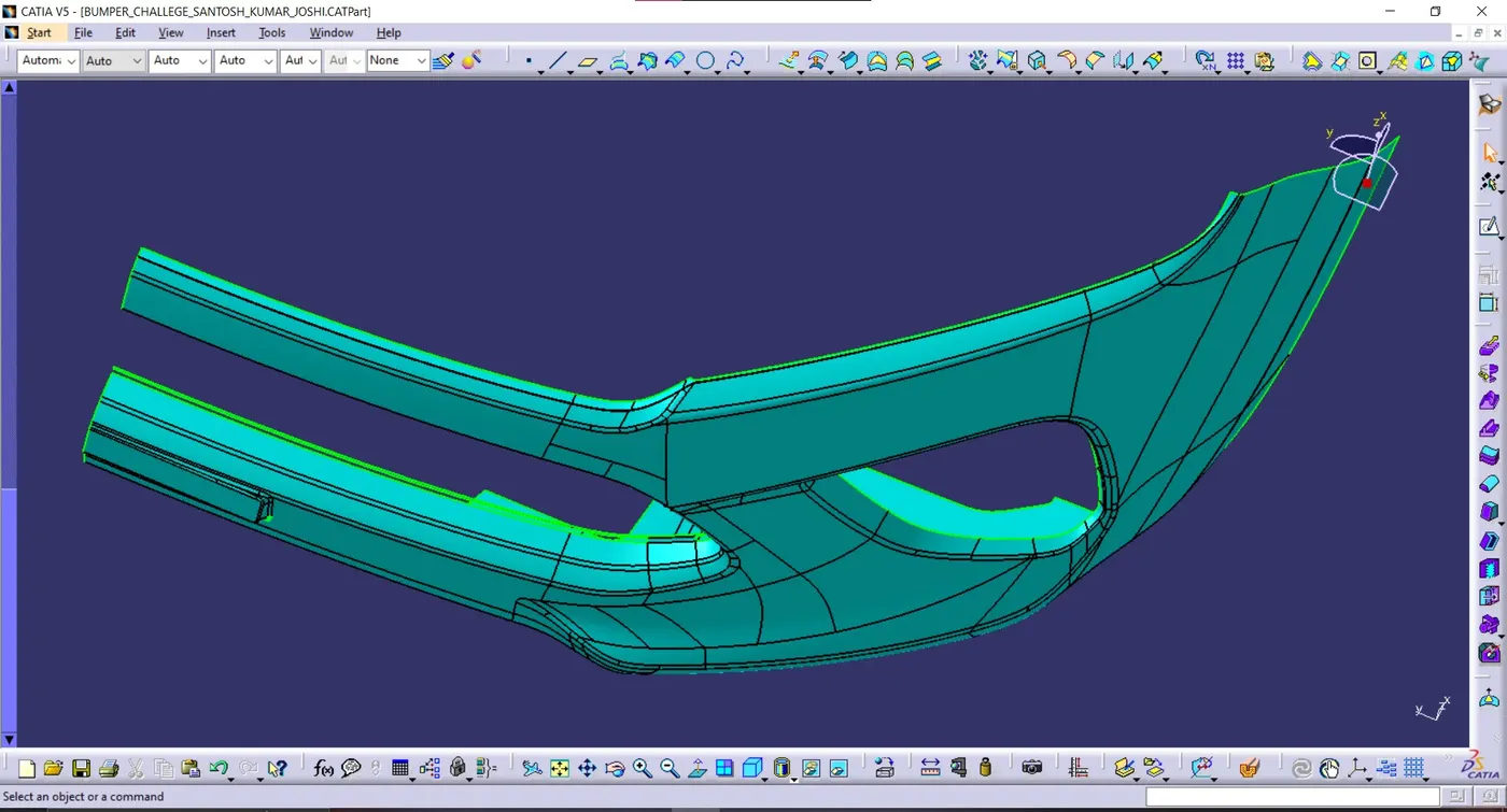
Here I work the following areas to create a Class B surface:-
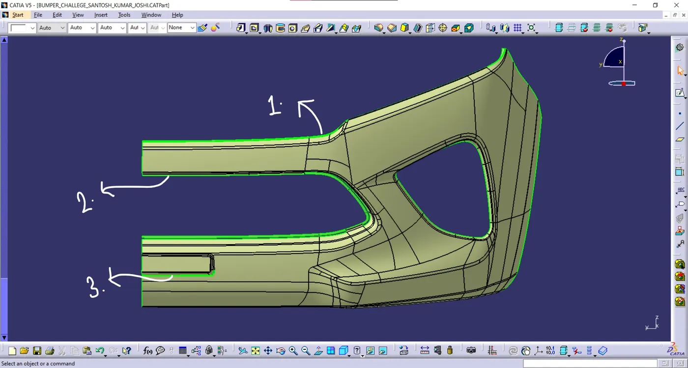
here above area 1,2 and 3 some gap is it. so i one by one resolve this.
WORKING 1 TOP PORTION:
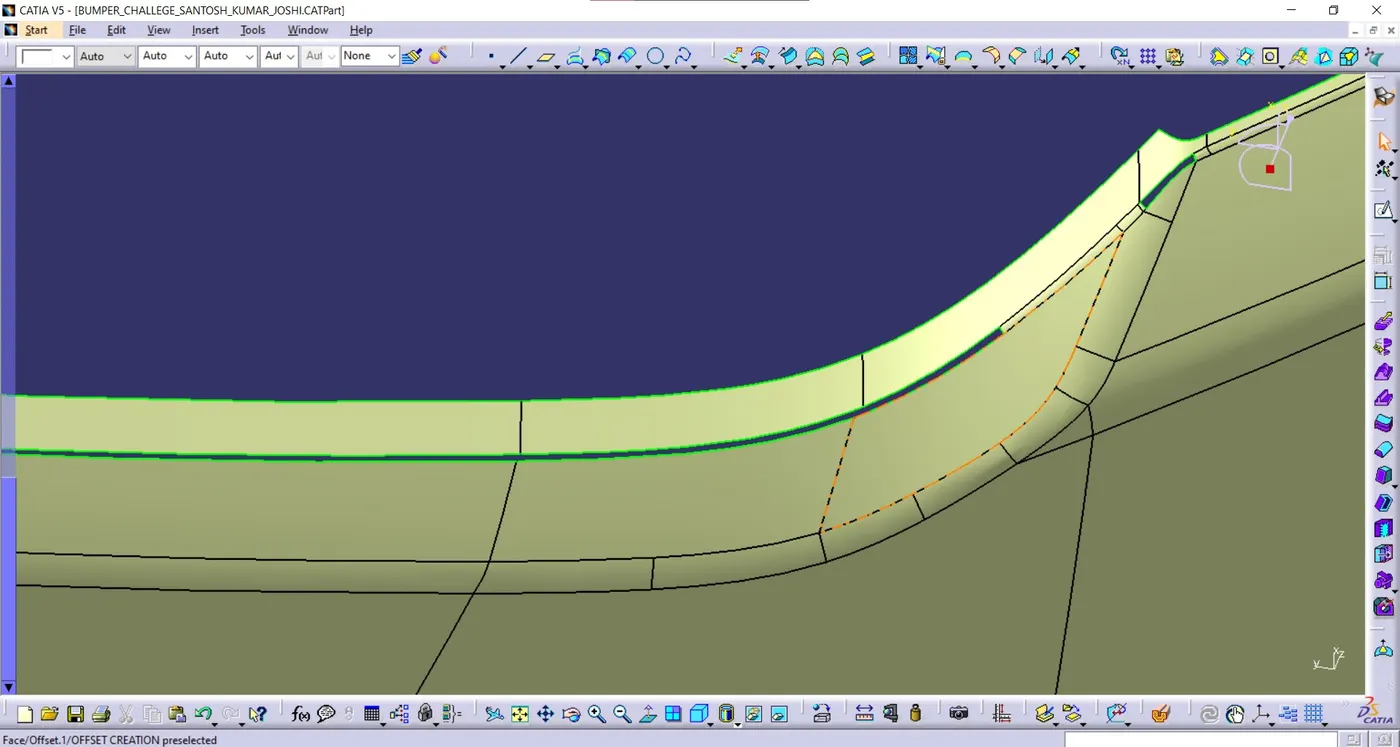
here i use some command to fill the gap.
• Multiple Extrect
• Boundary
• Extrapolate
• Trim
• Edge Fillet
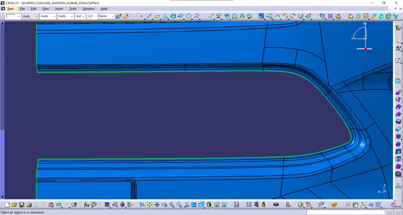
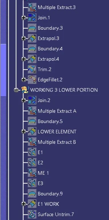
WORKING 2 MID PORTION:
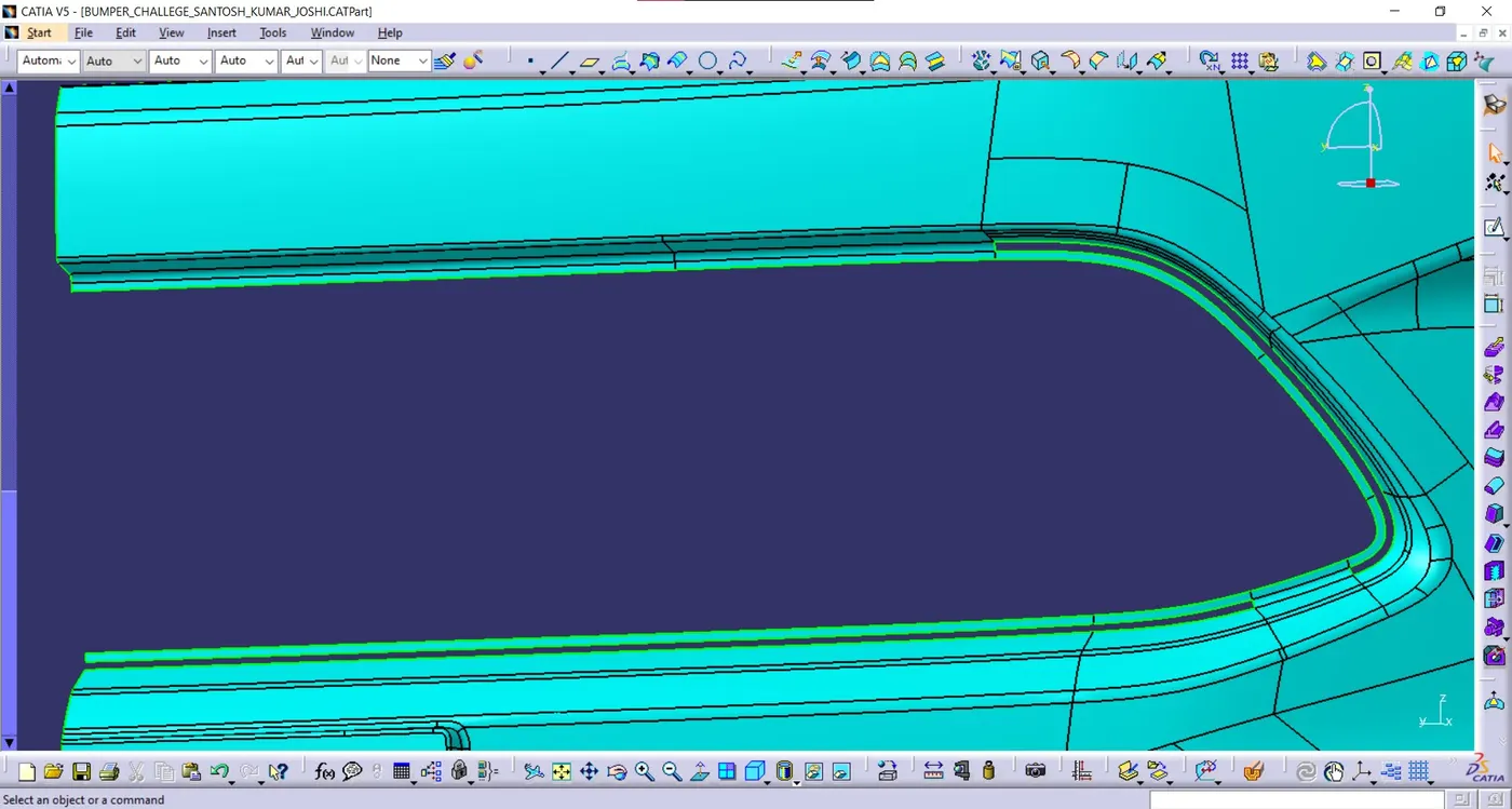
here i use some command to fill the gap.
• Multiple Extrect
• Extrect
• Join
• Boundary
• Extrapolate
• Trim
• Edge Fillet
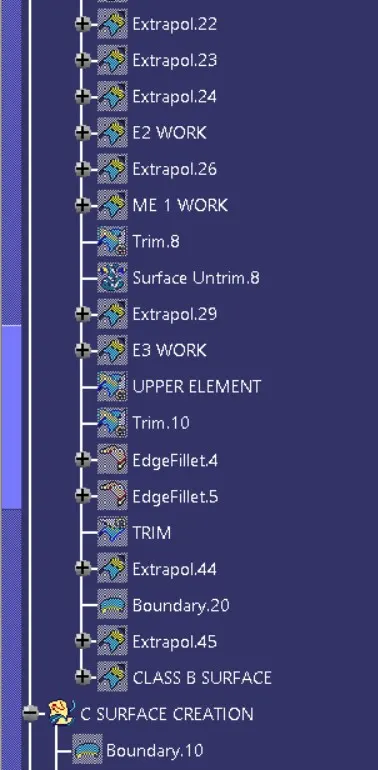
WORKING 3 LOWER PORTION:
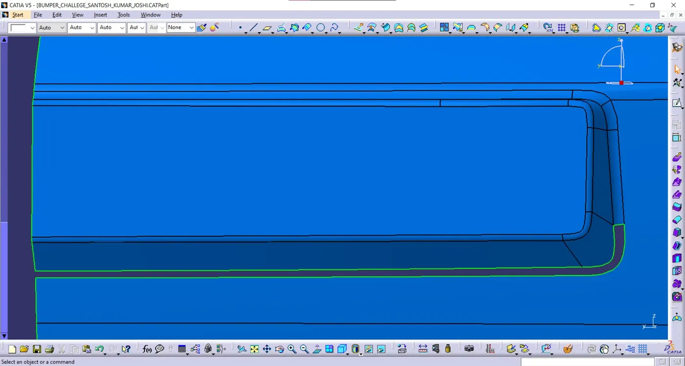
here i use some command to fill the gap.
• Join
• Multiple Extrect
• Extrect
• Boundary
• Extrapolate
• Un Trim
• Trim
• Edge Fillet
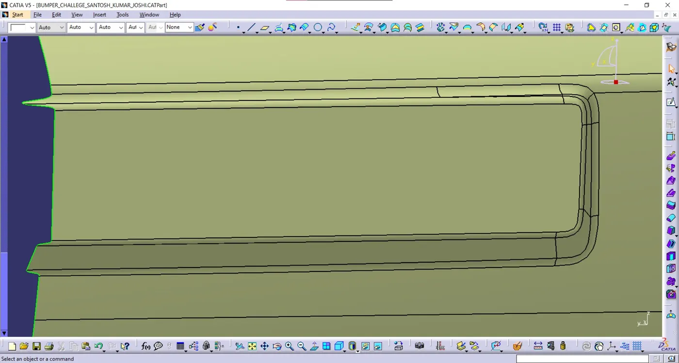
Here the below image is class B Surface.
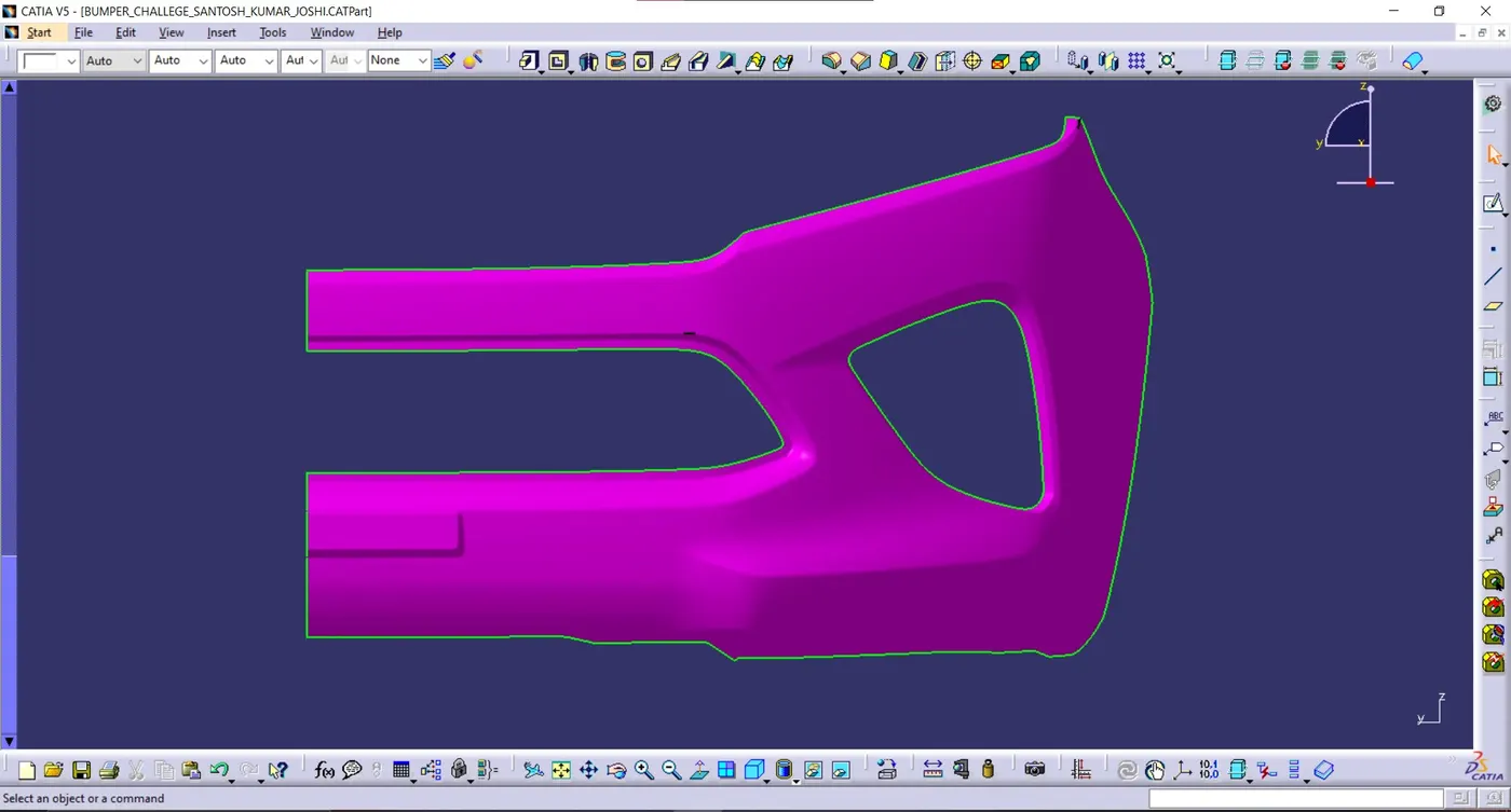
CLASS C SURFACE:
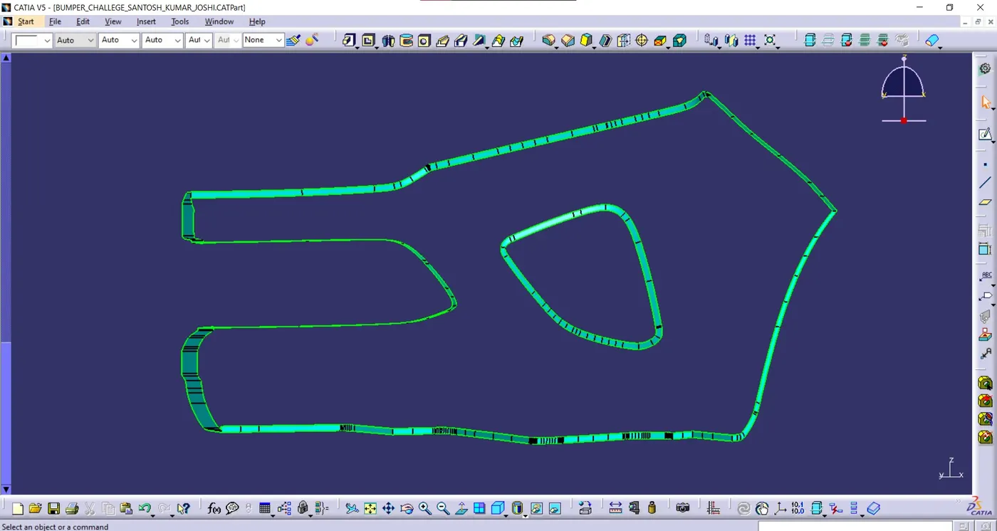
• Class C surfaces are connectors between Class A and B surfaces.
• This surface connects both A and B surfaces along the Tooling Axis.
• It contains the draft as per the design.
• It is basically the thickened surface between both A and B surface.
here i extract the boundary of class a surface.
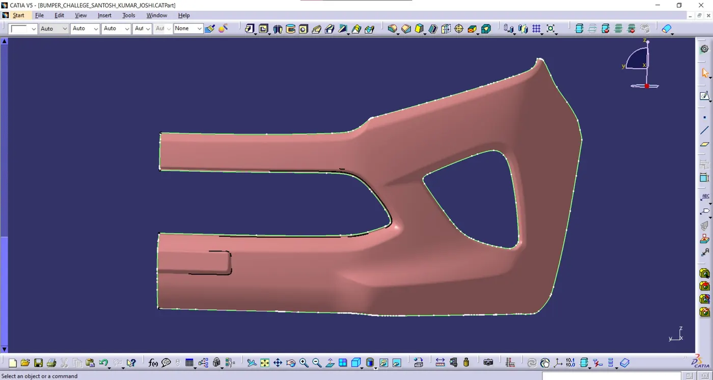
then i use these command to creat c surface.
Boundary
Sweep
Extrapolate
Trim
Here the below image is class C Surface.
JOIN A AND C SURFACE:
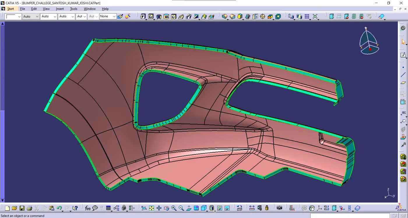
Here the below image is join of class a and class C surface.
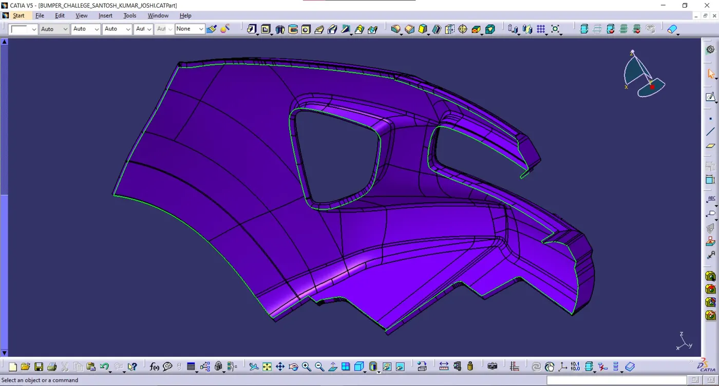
FINAL TRIM:
here the join trim with class B surface.
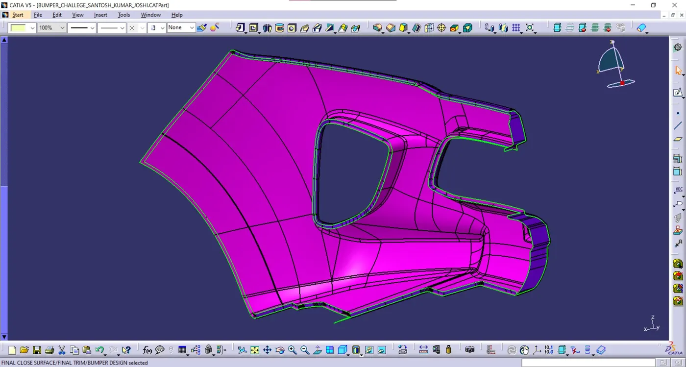
here the below image is final close surface
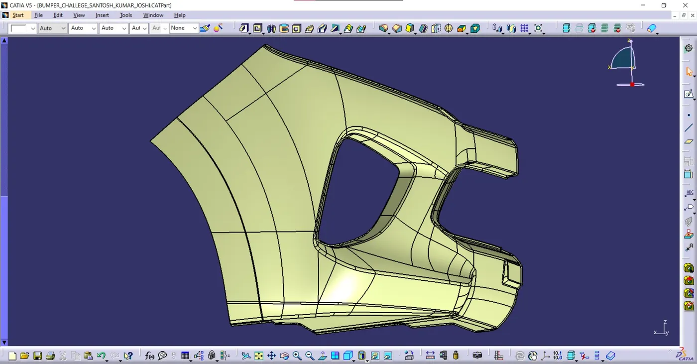
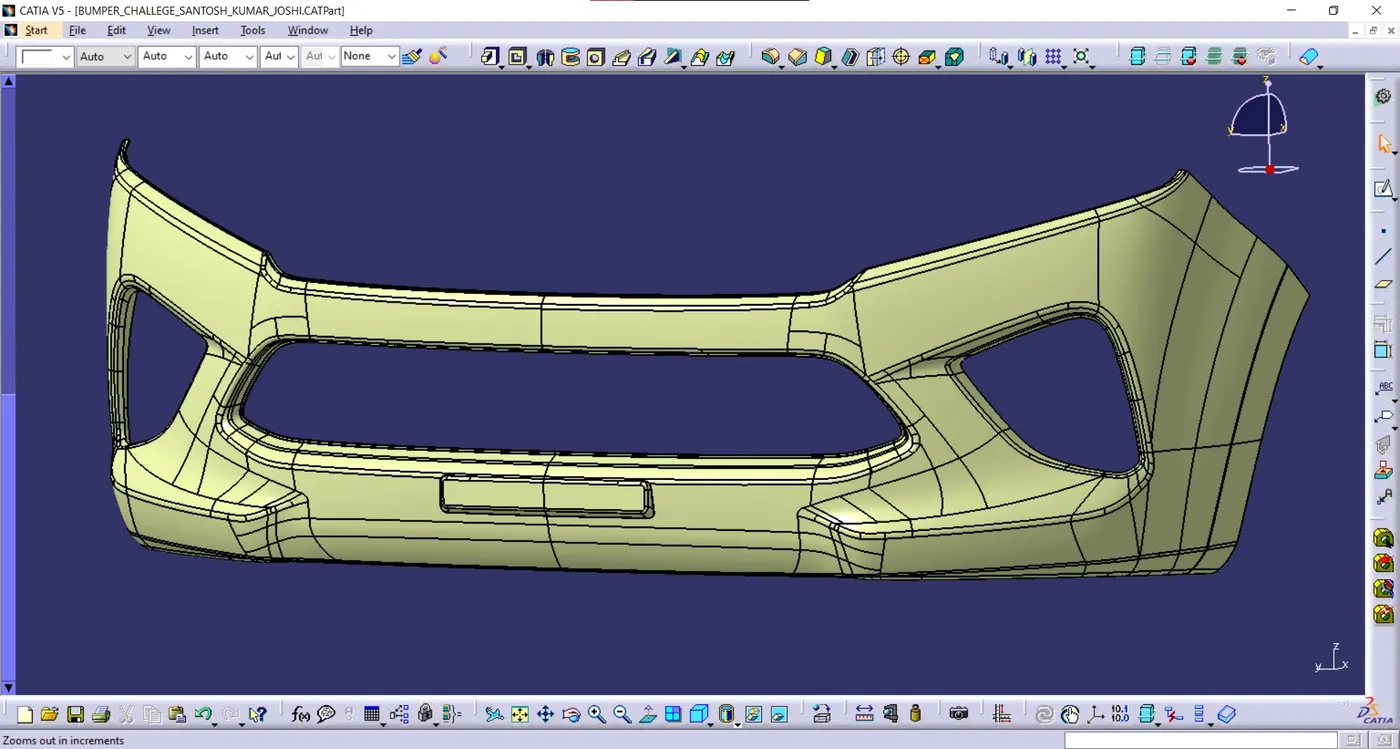
PART BODY:
Here i select final close surface by using closed surface option and get final plastic components.
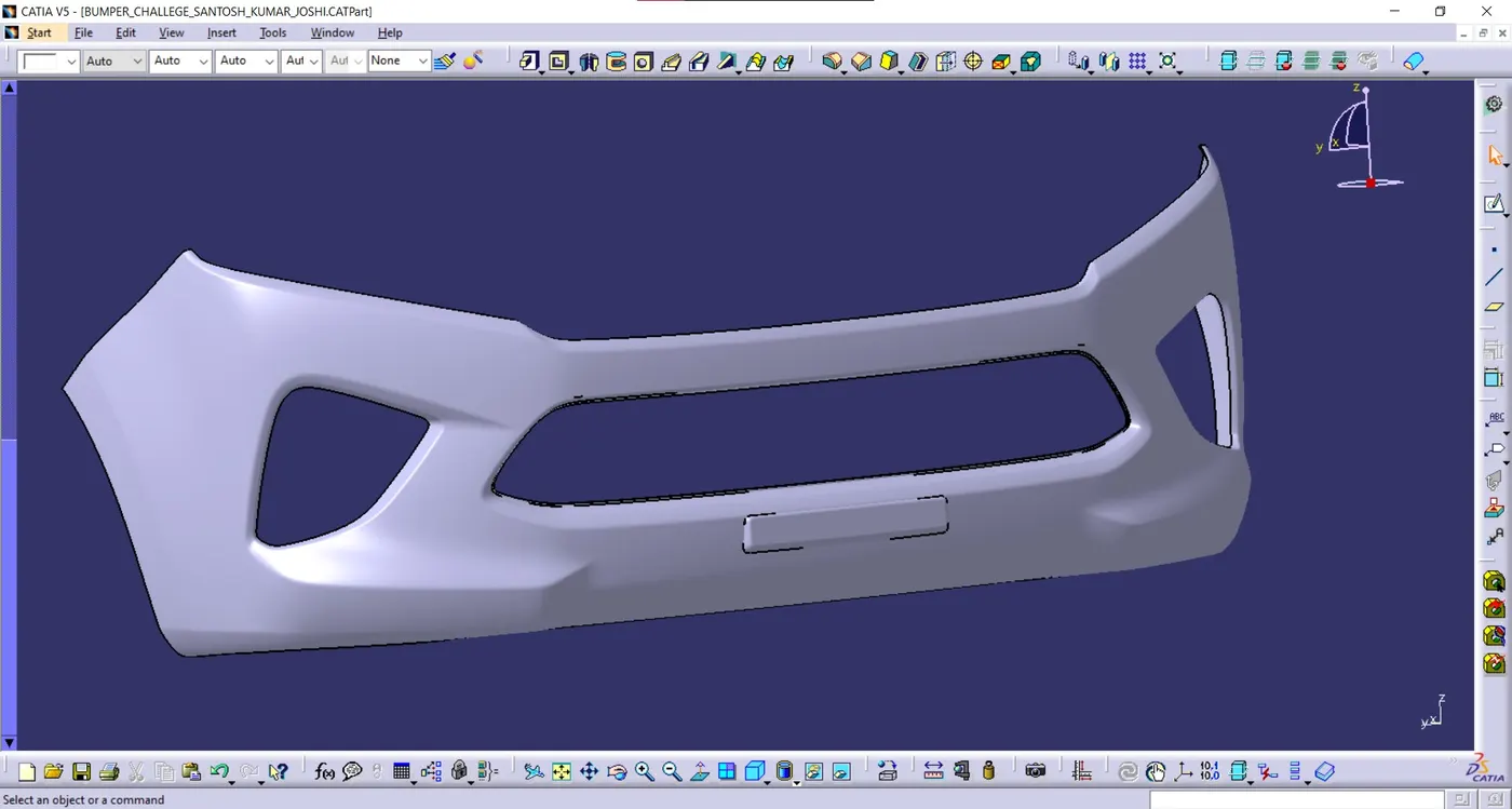
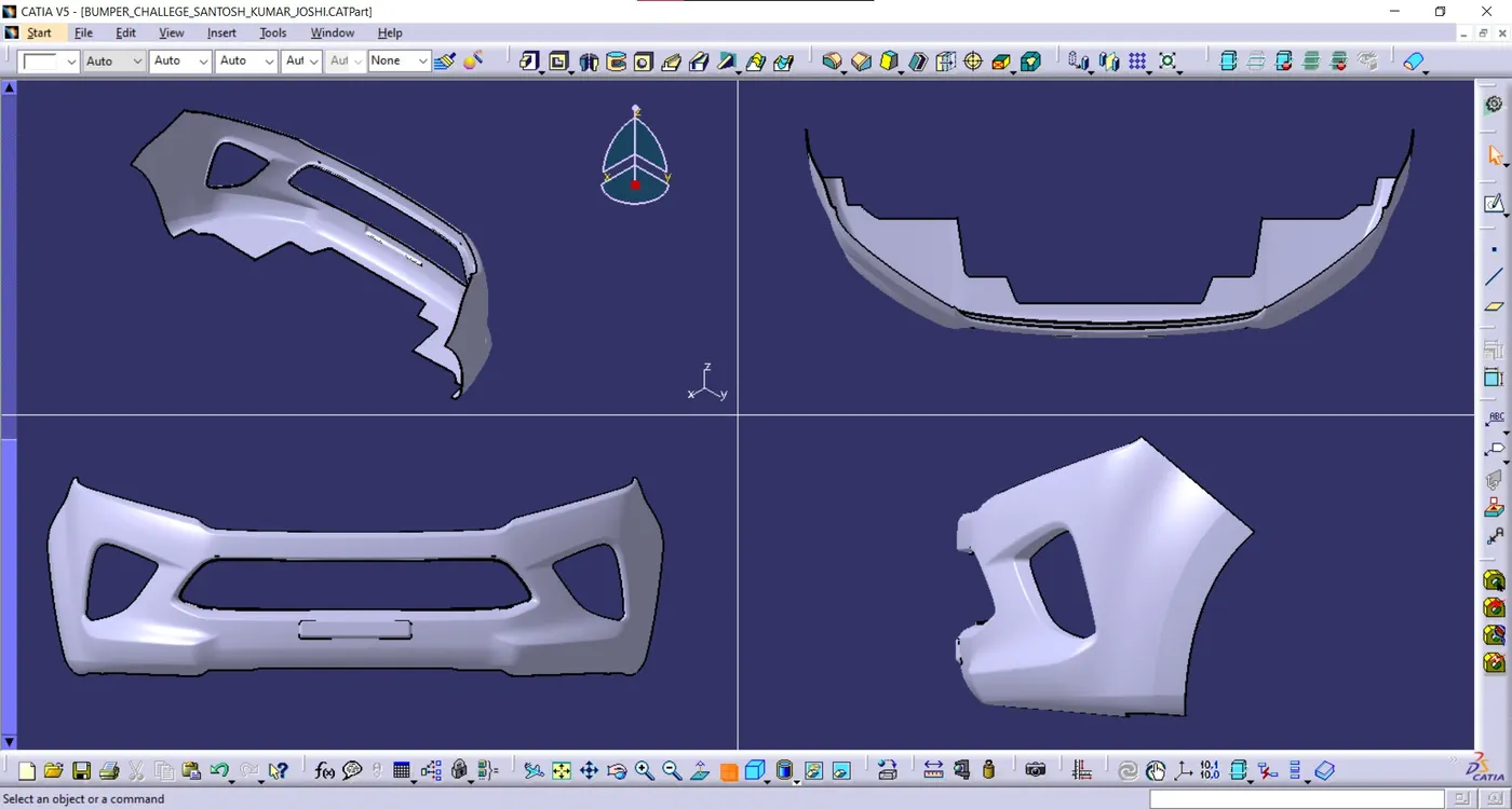
Here below on the image isometric, front, side and top/bottom view available.
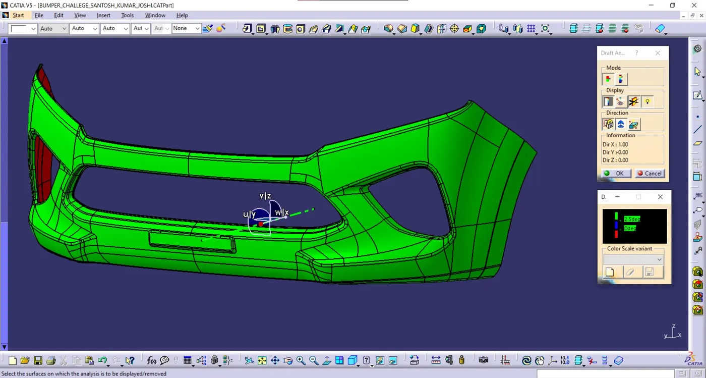
DRAFT ANALYSIS FOR FINAL PLASTIC COMPONENT:
• Draft Analysis is a tool in CATIA which identifies the zones which deviates from the specified values of angles along a defined draft direction using colour codes.
• It highlights the regions of draft using colours.
• Draft analysis is the first step performed after receiving the Class A of the component.
• Draft analysis should be passed in order to make the plastic component manufacturable.
• Acceptable draft angles are used as range for draft analysis that is 0 to 3 degree. and here i provided 2.5 degree of draft.
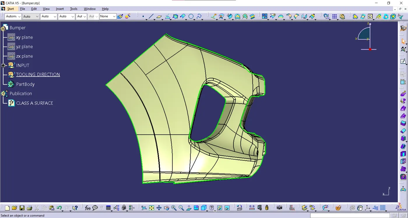
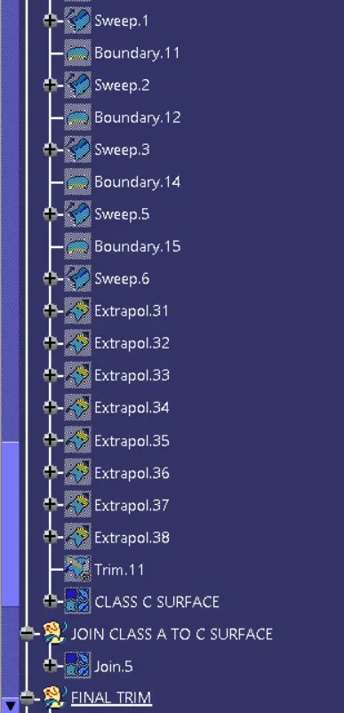
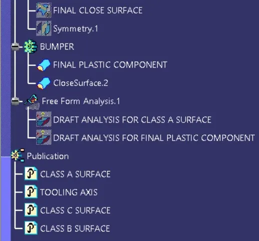
TREE STRUCTURE:
CONCLUSION:
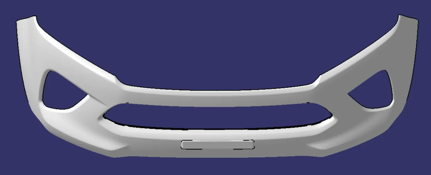
Finally the Class – A, B & C surfaces with the Tooling Direction have been Published and the bumper is moved on to the designing of the next operation – the creation of other features.