Week 9 - Challenge 2 - Switch Bezel Design
AIM:
Create the Switch Bezel Plastic component through the given Class-A surface. To begin with, the tooling axis for the given Class-A Surface should be created meeting the requirements of the draft angle and at the end perform the Draft analysis on the model.
INTRODUCTION:
The draft analysis technique is used to analyze whether our part model created in CAD is manufacturable based on the draft condition applied. Here the part should get easily removed from the panel dies (in case of Sheet metal part) or Mold (in case of plastic).
CLASS-A SURFACE: the class-A surface is used in the automotive design industry. it describes the final production surface data for the aesthetic parts.
CLASS-B SURFACE: the class-B surface is the second surface that has a certain thickness from the class-A surface. this surface contains engineering aspects of a model. These must be smooth and "error-free" as well but are not held to the standards that class A surfaces are.
CLASS-C SURFACE: The Class C finish allows more imperfections than Class A or B. Class C is often specified for interior surfaces not readily visible, surfaces that will be covered by another part when assembled, or surfaces.
OBJECTIVE:
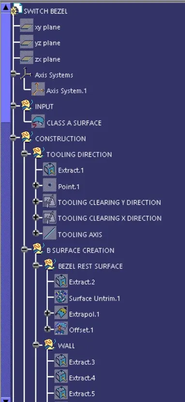
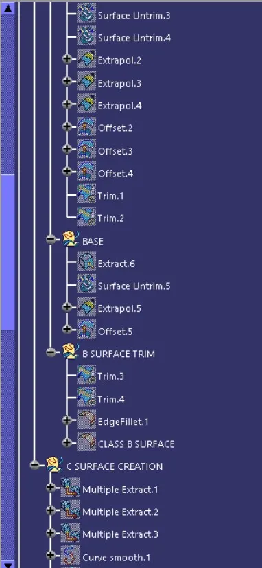
→ Ensure Proper Tree Structure.
→ Geometrical sets should have a proper name based on the sketches present inside them.
→ All the sketches should be created under the Geometrical set.
→ Use the Close Surface feature to make a solid body from the surface.
→ To publish the Tooling Axis, Class A, B, and C surface.
DESIGN METHODOLOGY:
Insert the class A surface of the switch bezel in CATIA software.
Determining the tooling axis for the switch bezel
Creation of class B surface.
Creation of class c surface.
Join the switch bezel's class A, class B, and class c surfaces and ensure all the surfaces are closed surfaces.
Use the Close Surface feature to make a solid body from the surface.
finally, Perform the Draft analysis on the switch bezel final plastic component.
CLASS A SURFACE:
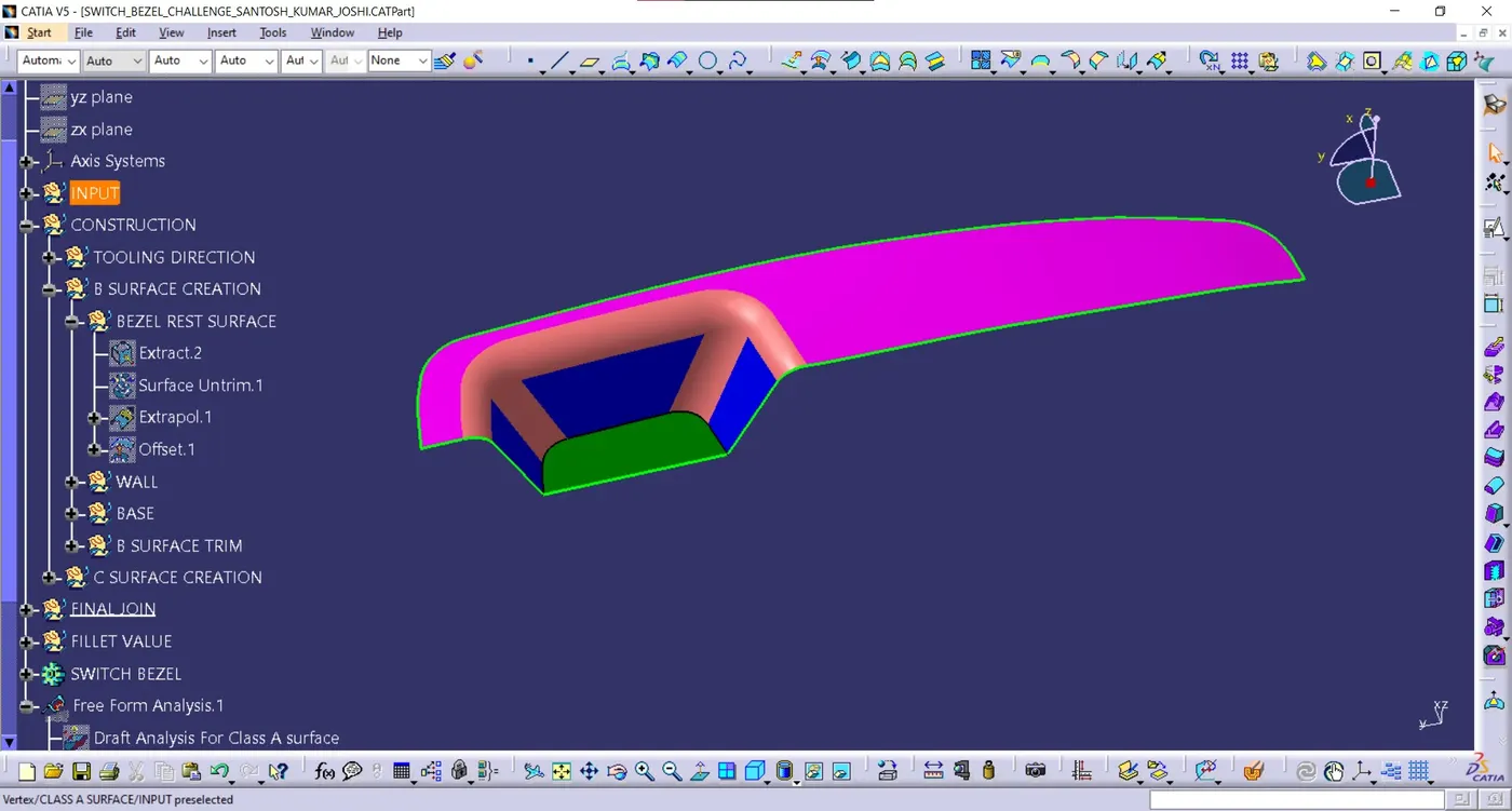
TOOLING AXIS CREATION:
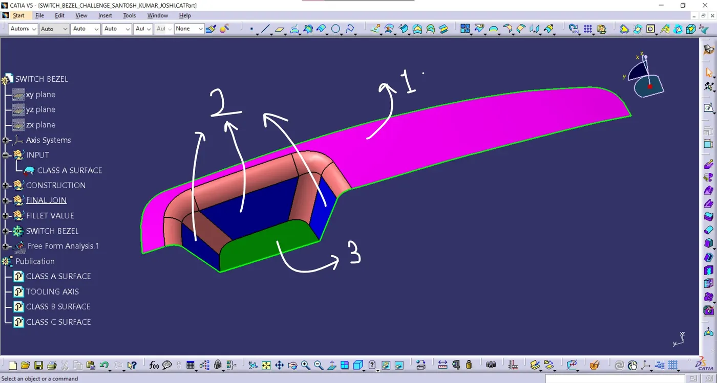
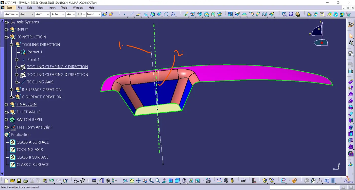
Here i decided to choose lower base of the Class A Surface to create tooling axis. like you can see below image 3 no.
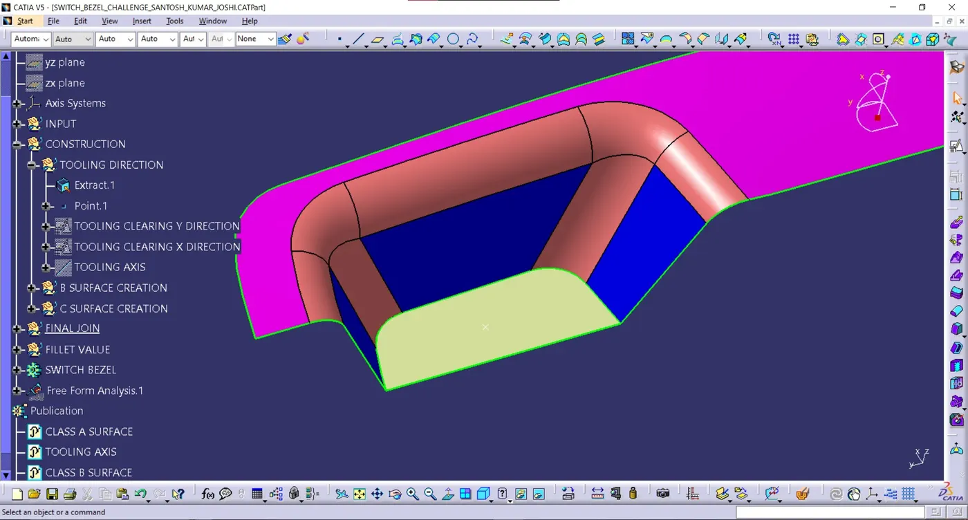
Then i extract the base of class a surface.
Then i select the point to get the axis system. and going to the positioned sketch.
Here I use the Project 3D element option to get intersect profiles by selecting the yz plane, which lies in the class a surface.
Then I draw dummy lines on both sides on the profile. And using bisect line option select this line and get tooling clearing line in y direction
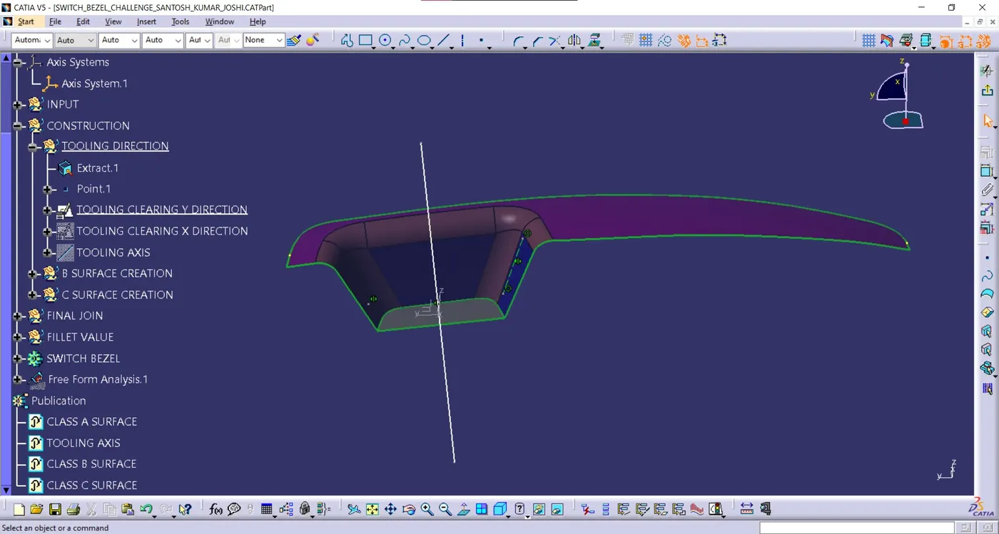
Here there is no wall in front of it, so I select the zx plane to get the profile using the Project 3D Element option. And draw line on this profile and draw another line from origin point to z direction. And the distance between these lines is 5 degrees.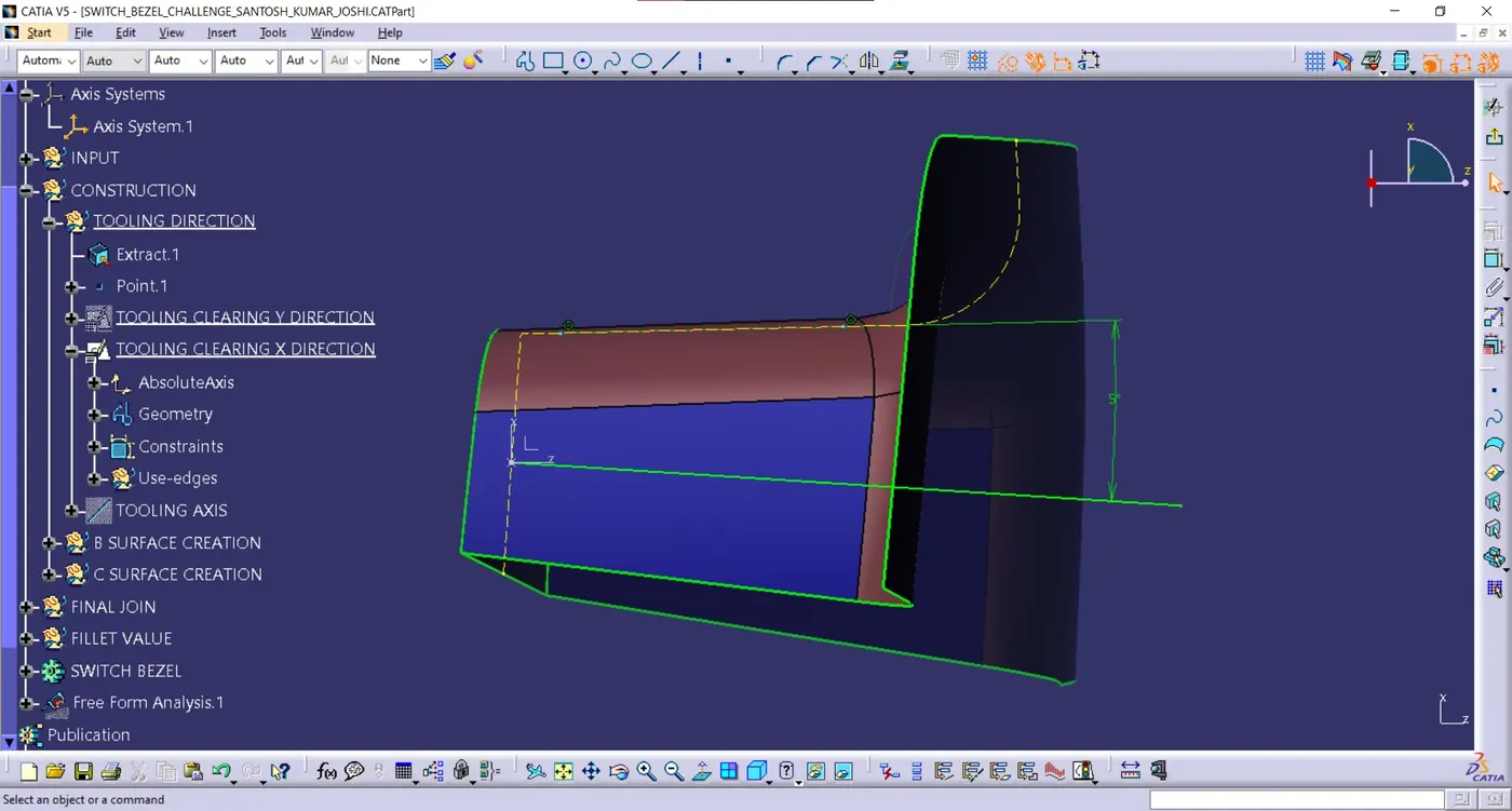
then i select both the line, and point using bisection line option to get tooling axis.
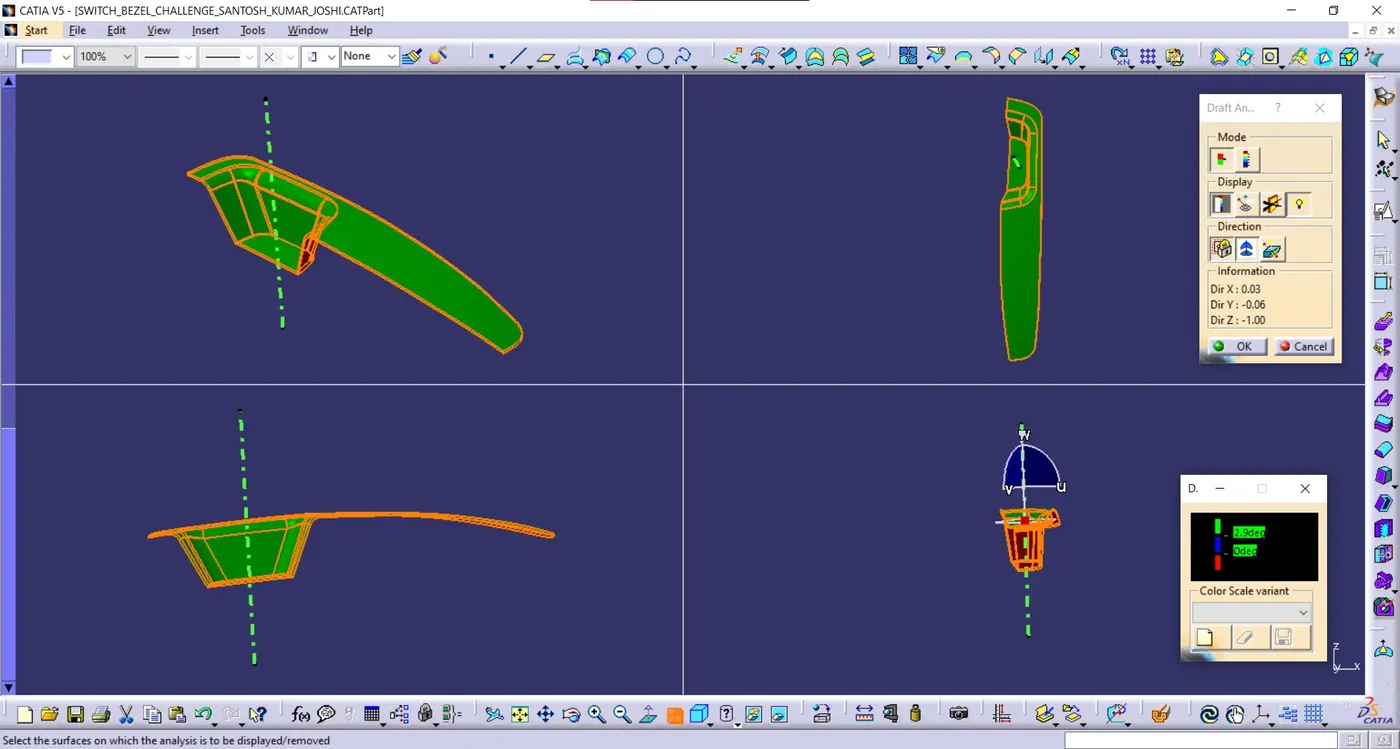
DRAFT ANALYSIS FOR CLASS A SURFACE:
Go to insert< analysis>
Align the tooling axis with the compass.
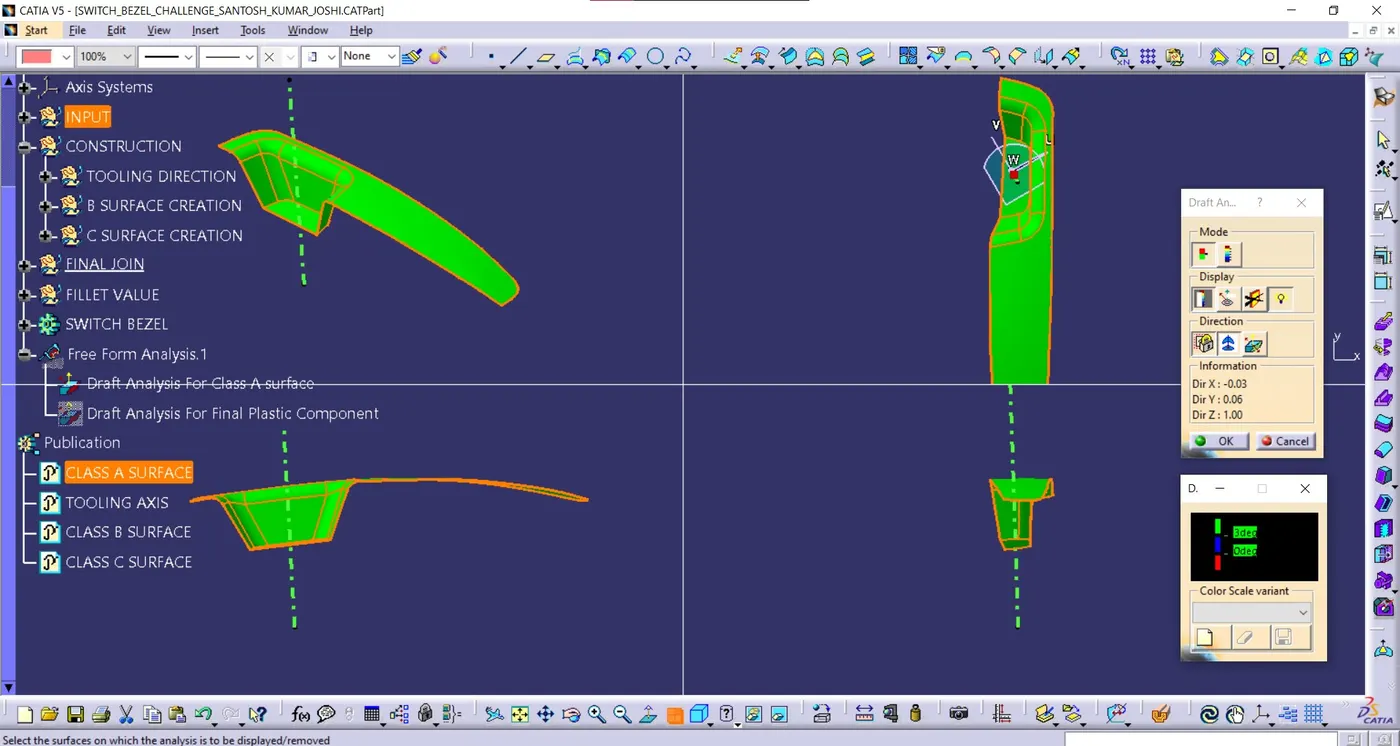
Click on the surface and see that the surface is within the permissible limit of the draft values.
The surface should be green and in the column proper value (3deg) should be inserted.
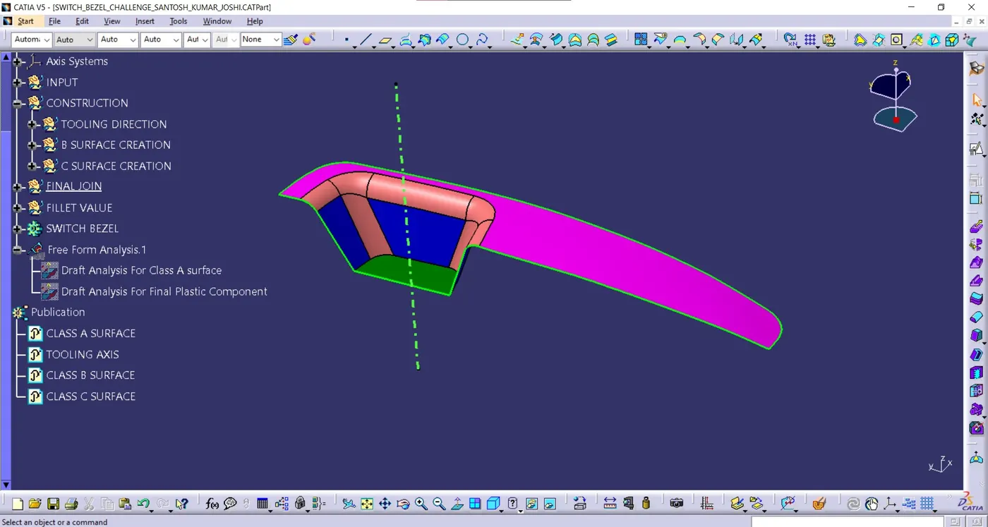
HERE BELOW ON IMAGE ISOMETRIC, TOP, SIDE AND FRONT VIEWS IS IT.
B SURFACE CREATION:
HERE WE ARE FOLLOW 4 STEPS TO FOLLOW TO GET B SURFACE.
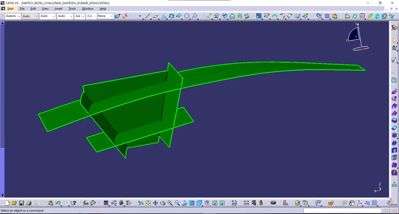
1. BEZEL REST SURFACE
2. WALL
3. BASE
4. B SURFACE TRIM
You can see in the image below.
1. BEZEL REST SURFACE:
Here i first Extract the surface.
Un-trim the surface.
Extrapolate it.
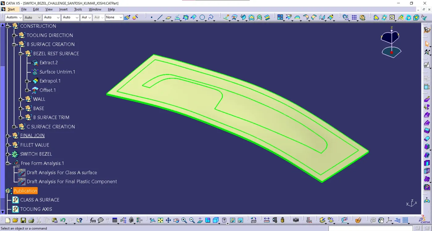
Offset it by 2.5mm i.e. thickness.
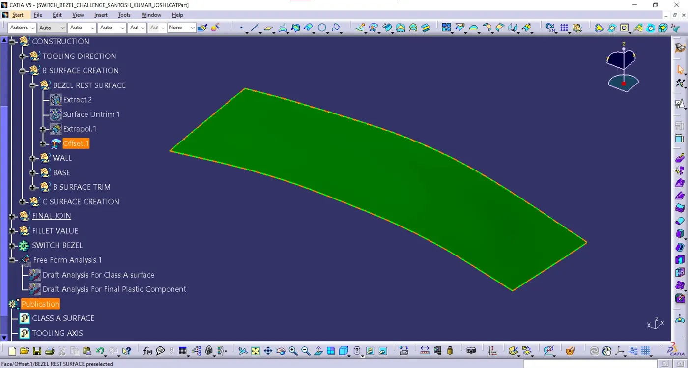
2. wall:
Here i first Extract the wall surface.
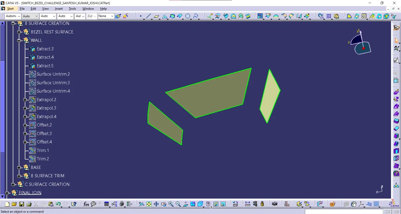
Un-trim the wall surface.
Extrapolate it.
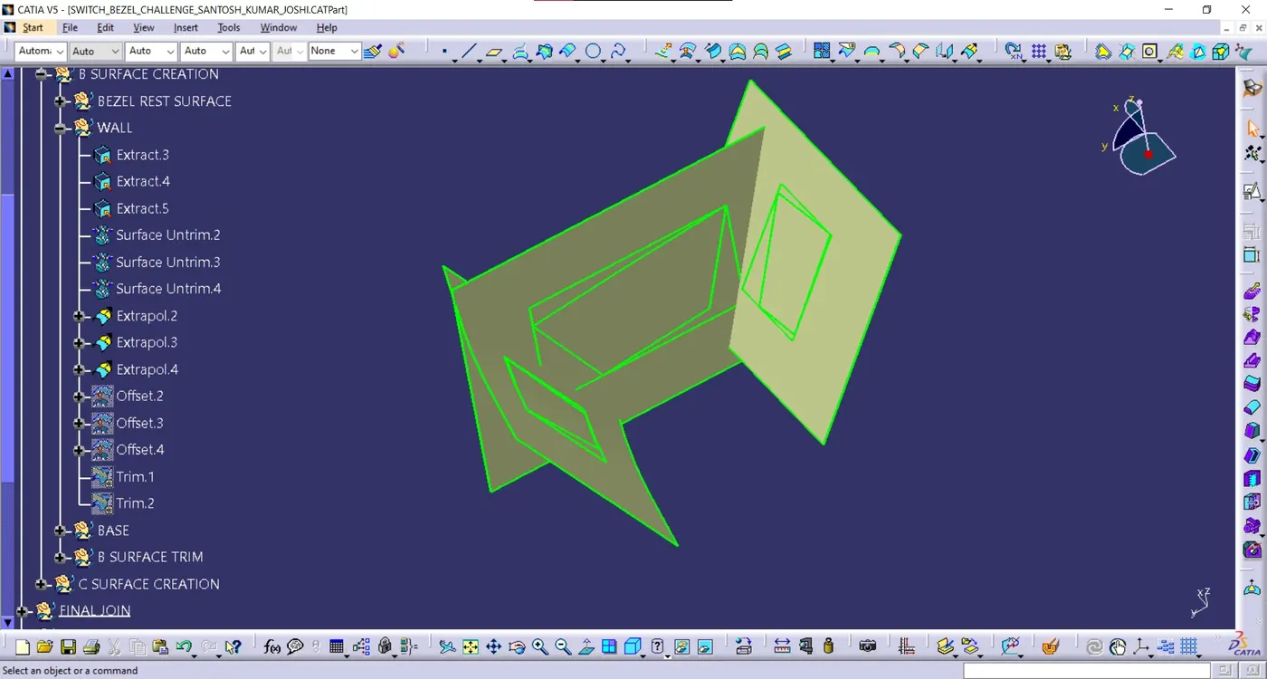
Offset it by 2.5mm i.e. thickness.
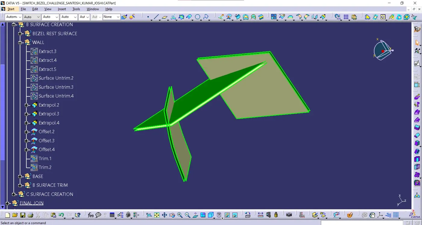
Trim to get the desired shape.
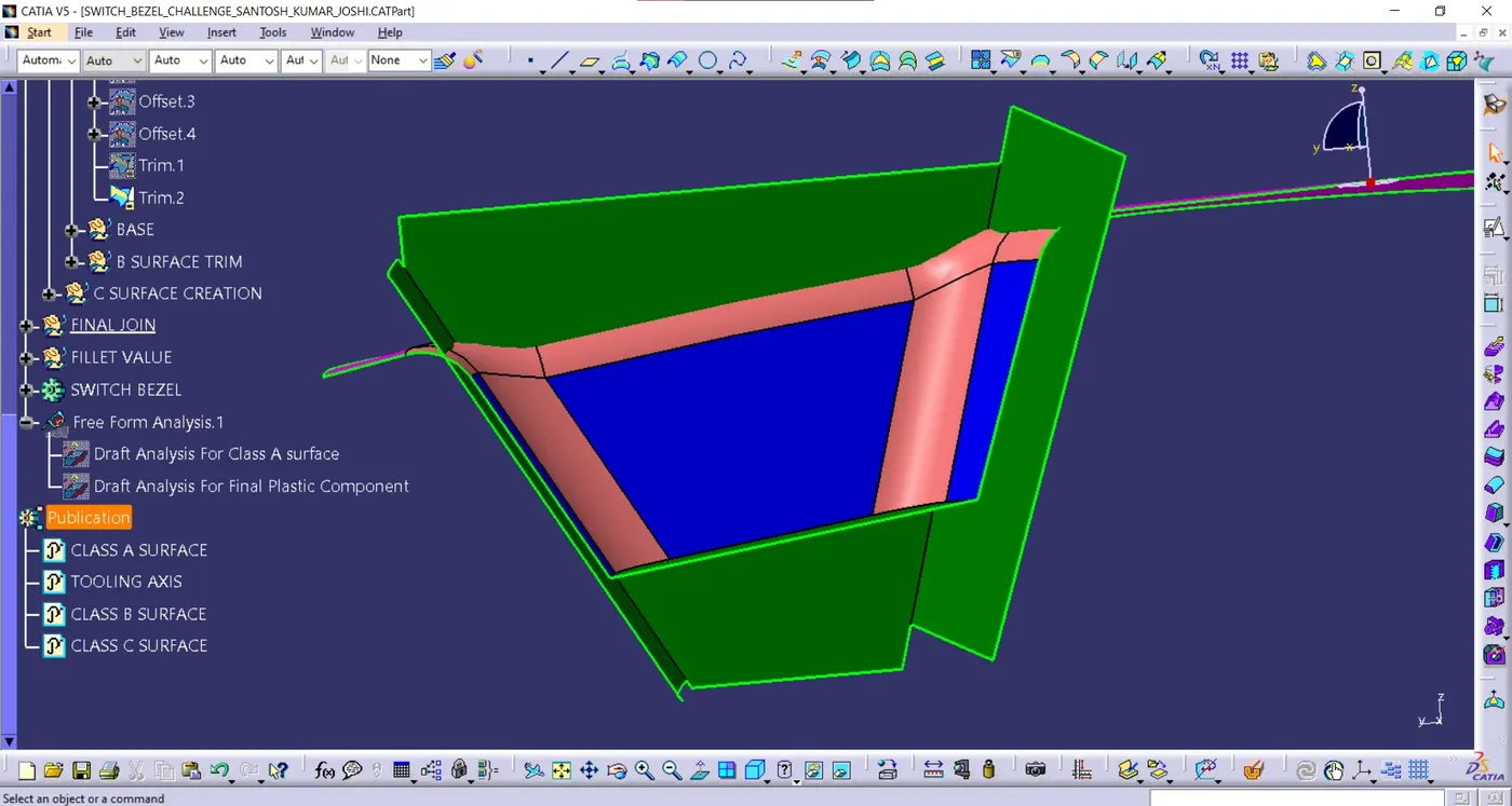
3. BASE:
Here i first Extract the base surface.
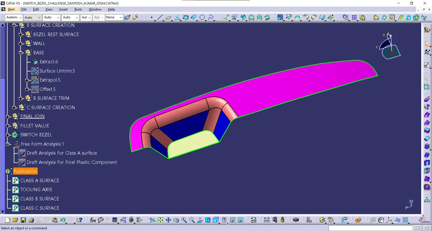
Un-trim the base surface.
Extrapolate it.
Offset it by 2.5mm i.e. thickness.
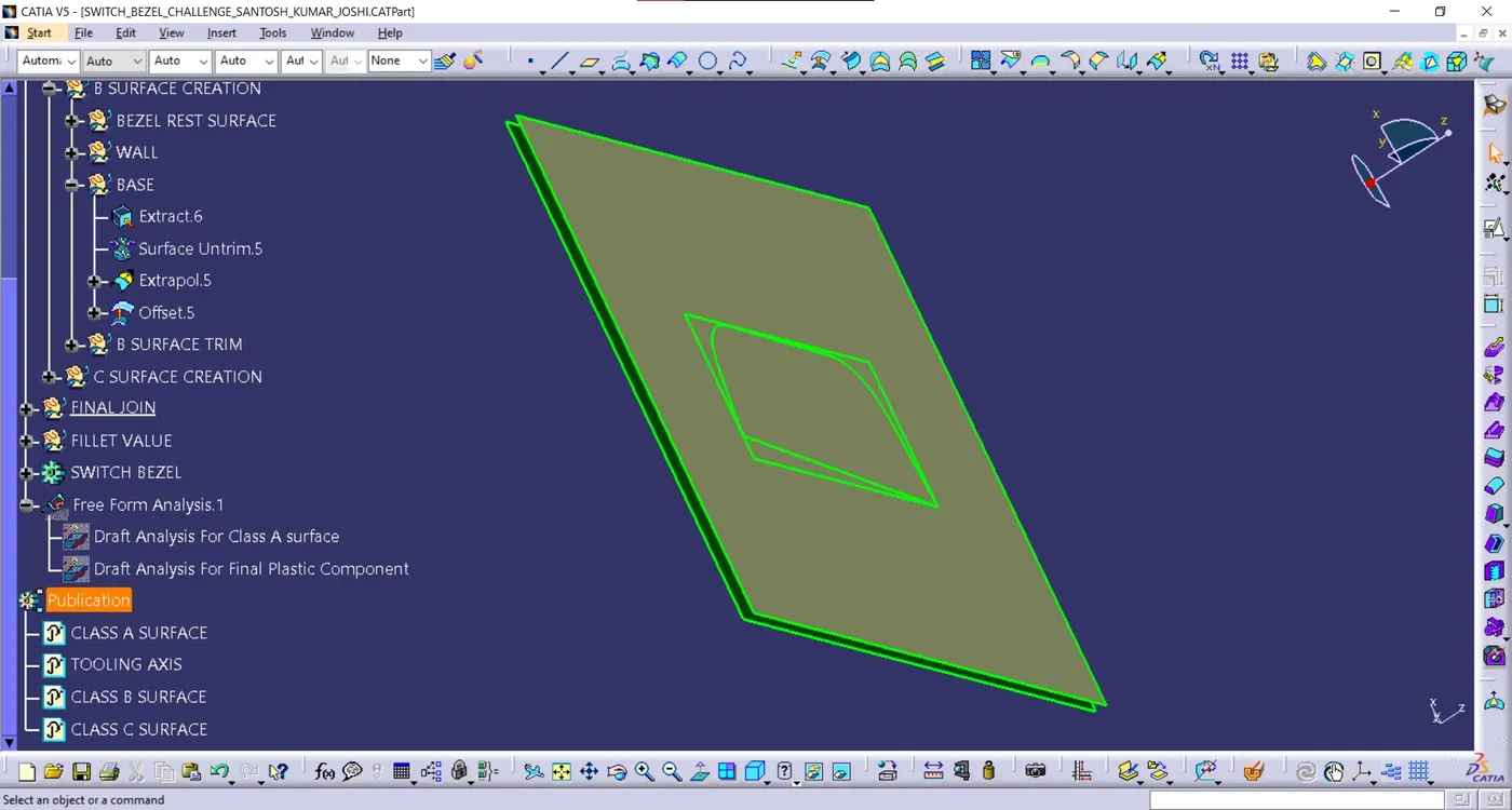
4. B SURFACE TRIM:
Here i first to trim bezel rest to wall and then trim the base and get the desire surface.
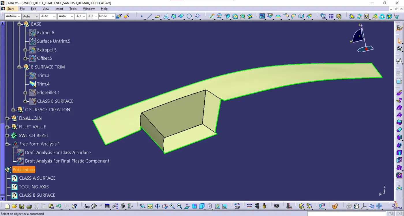
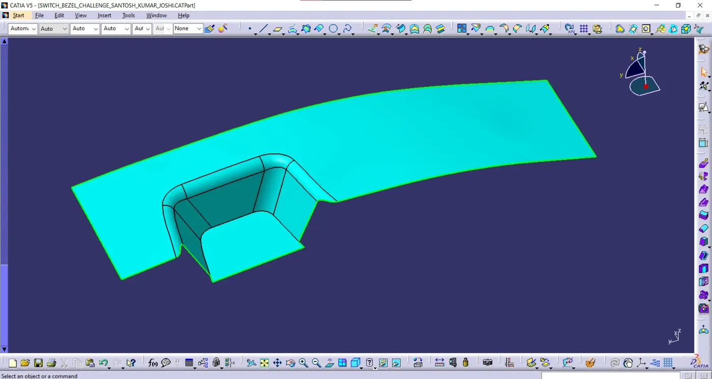
Then i provided fillet value by checking through class a surface fillet. and get final Class B surface.
C SURFACE CREATION:
here i first to extract the class a surface outer boundary. by using multiple extract option with tangent continuity.
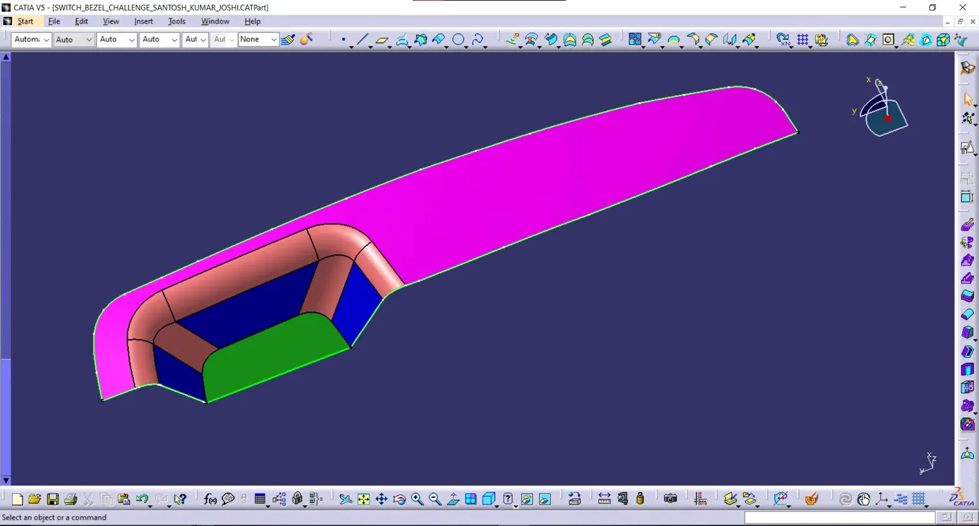
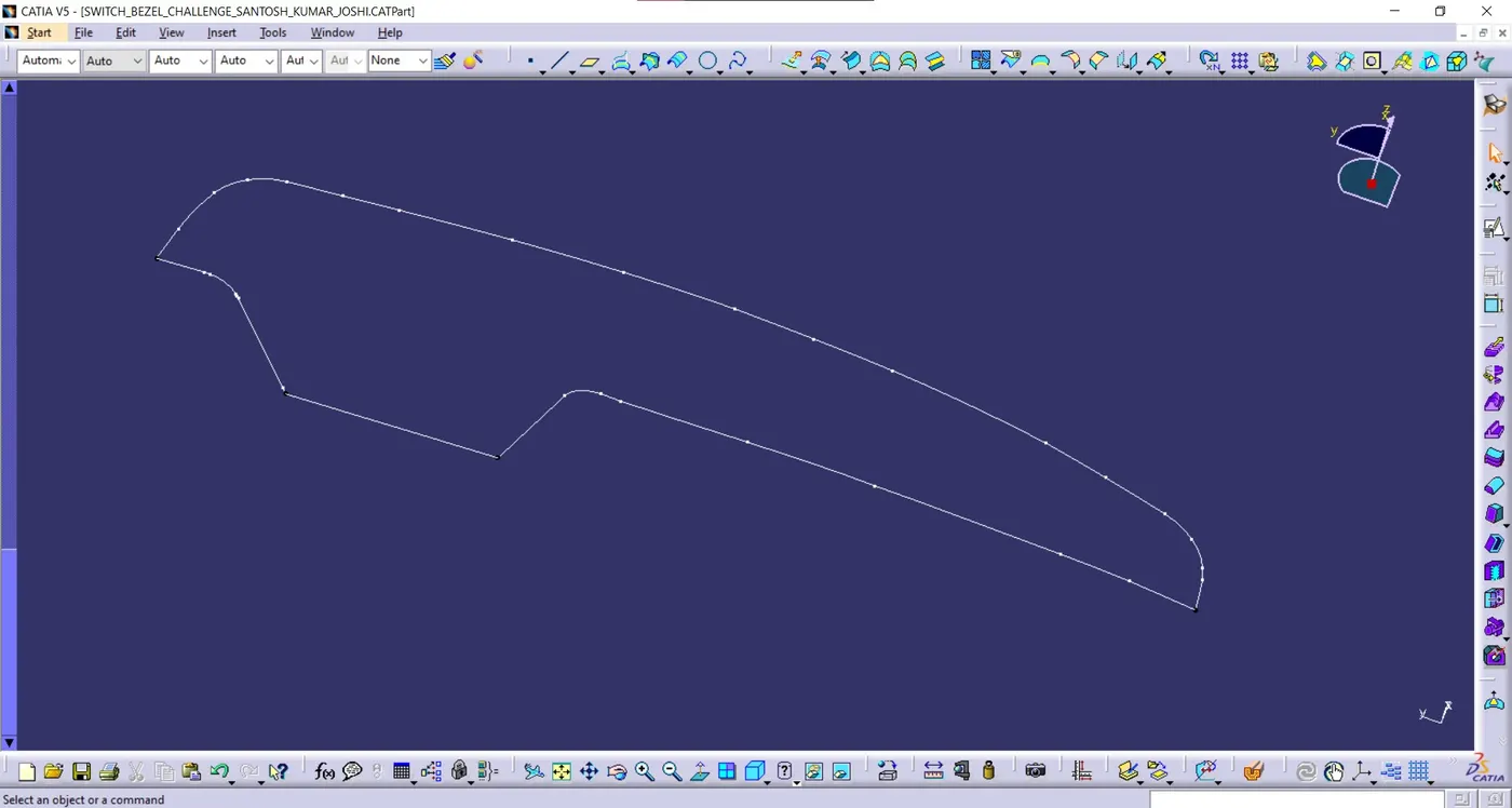
then select this profile one by one using curve smooth option to get smooth curve.
then go to sweep command one by one to select this profile and also select the tooling direction and given draft value is 3 degree and minimum thickness 5mm to provided it.
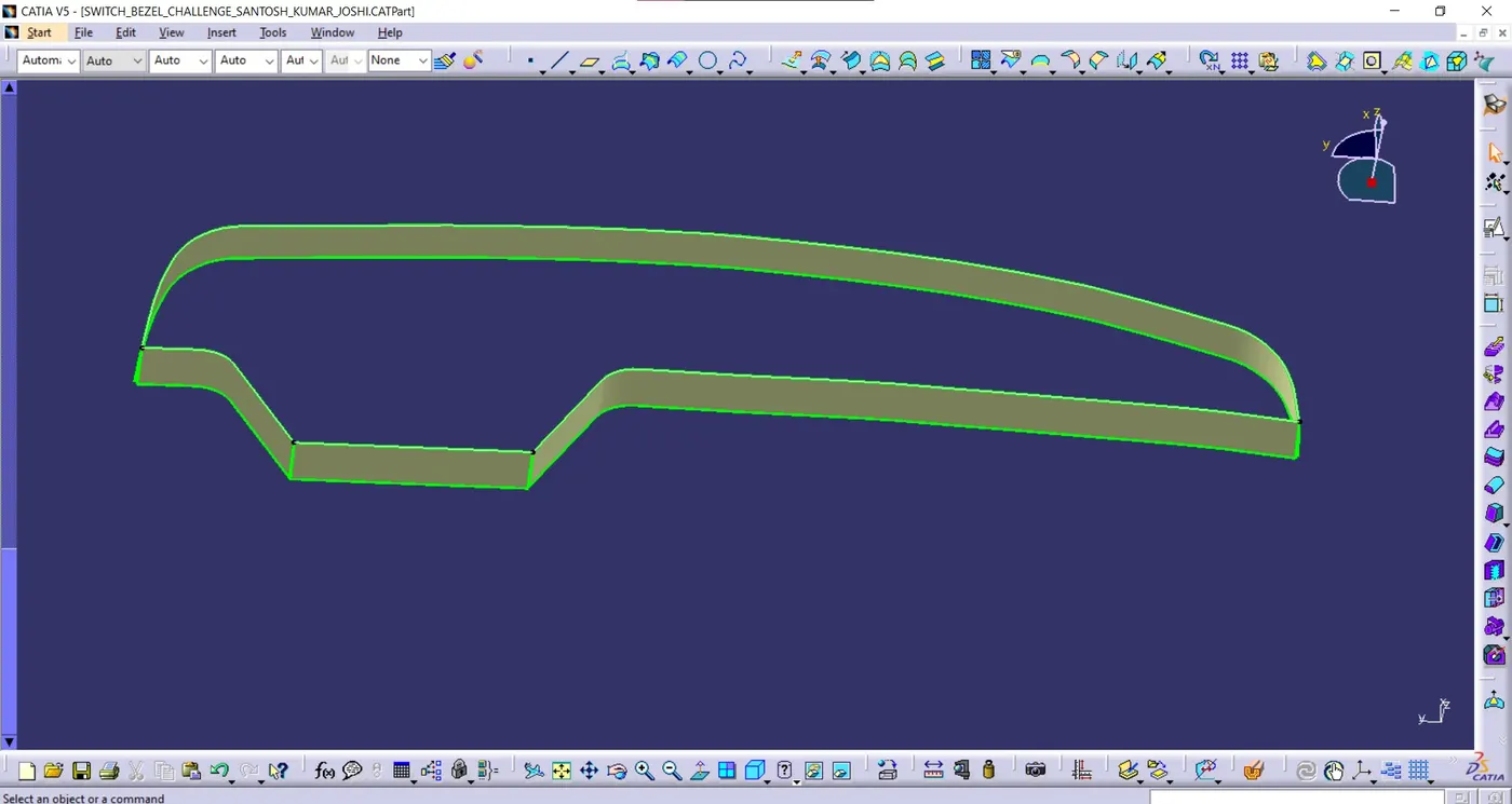
then extrapolate both side of each surface.
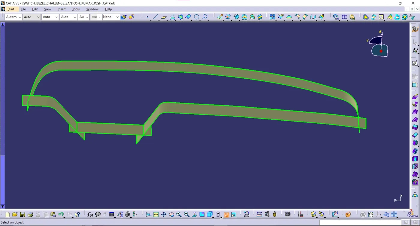
Then trim it, and get desired shape.
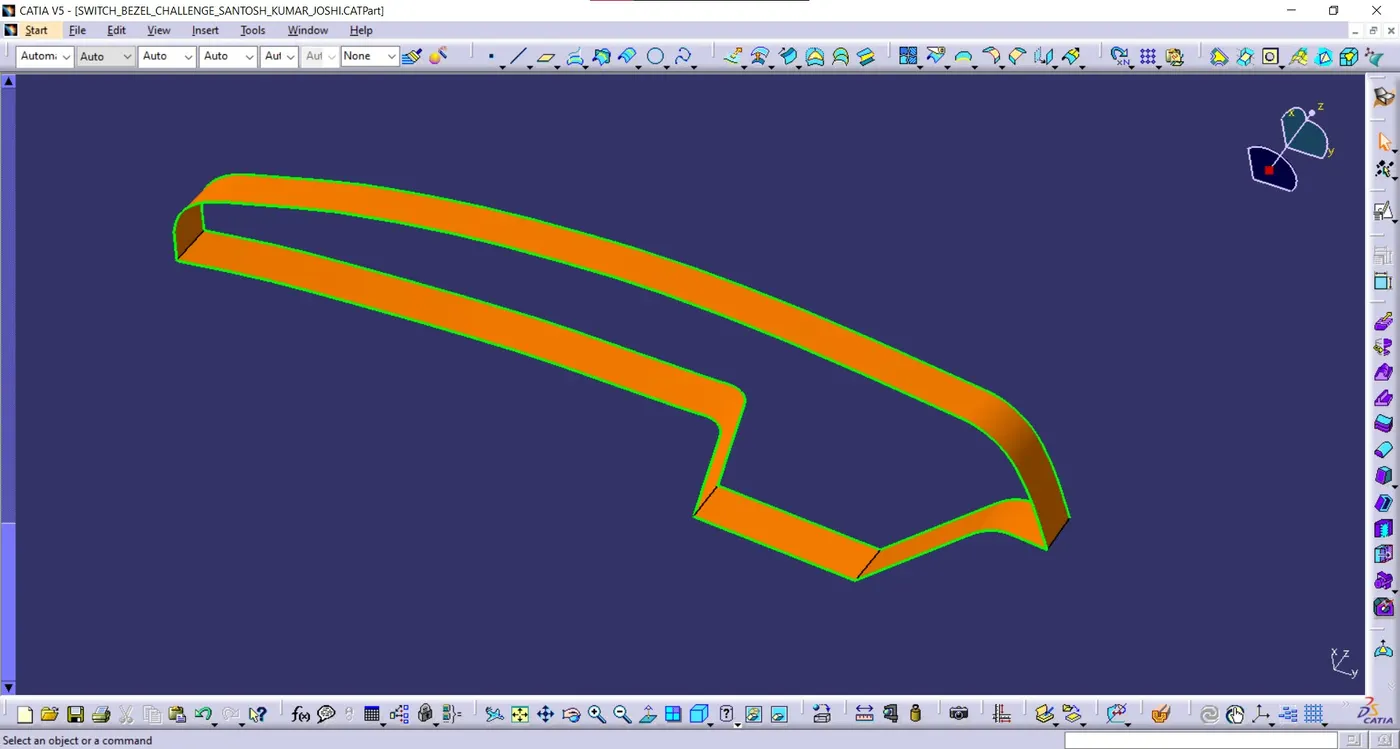
FINAL JOIN:
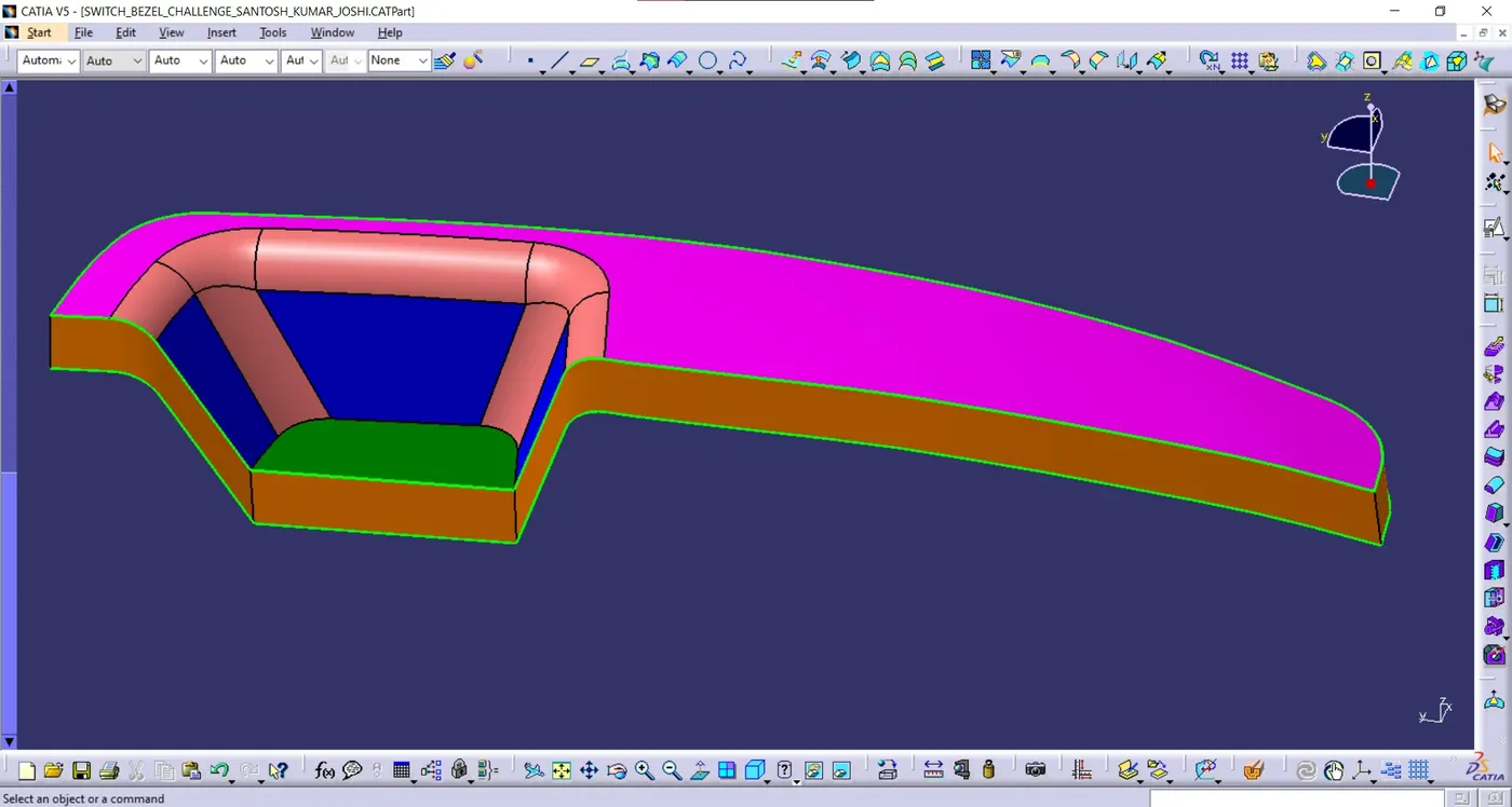
NOW WE HAVE CLASS A, CLASS B, AND CLASS C SURFACE.
First we are join Class A to Class C Surface, then trim with Class B Surface.
join A to C
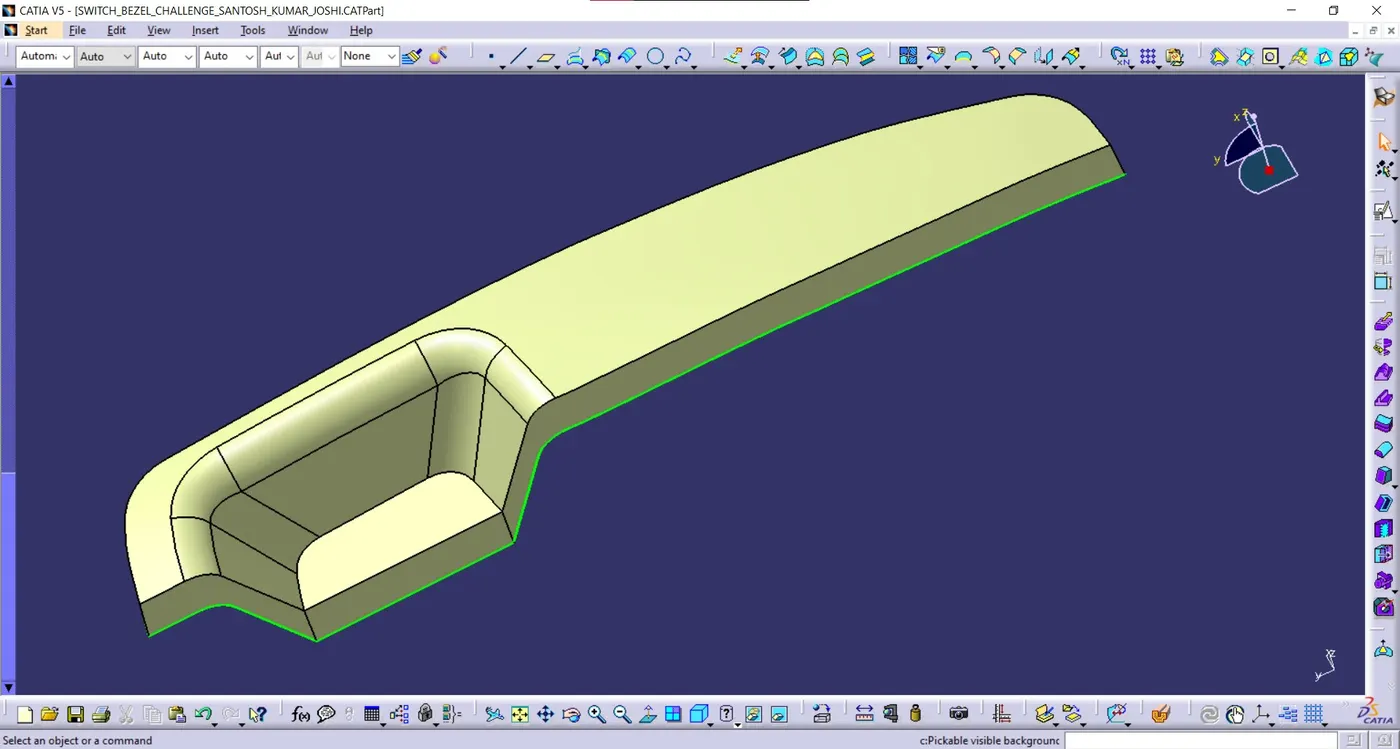
then trim with C
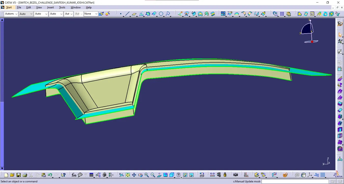
this is final thicken surface.
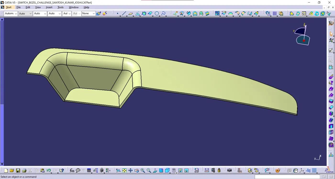
PART BODY:
Here i select final surface by using closed surface option and get final plastic component.
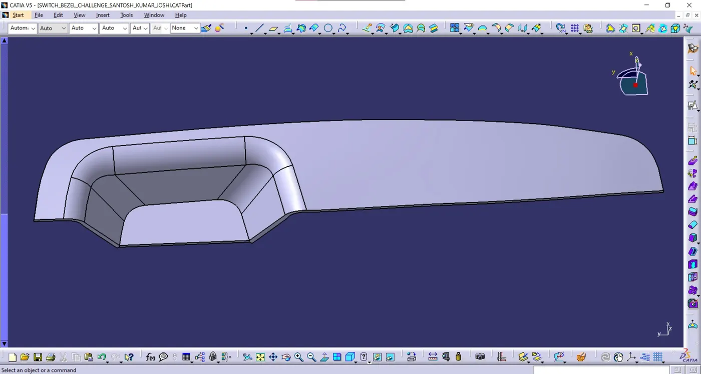
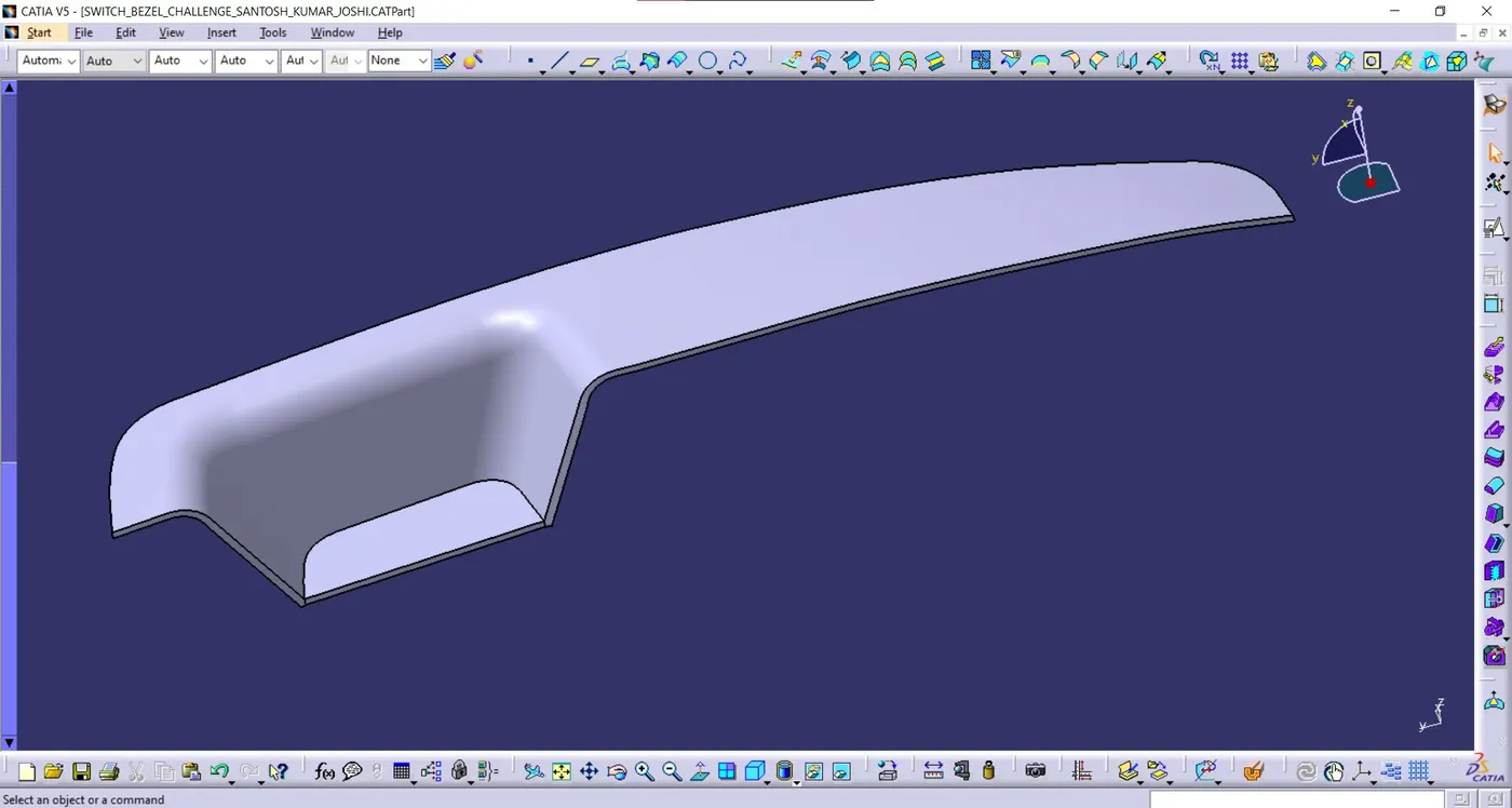
HERE BELOW ON IMAGE ISOMETRIC, TOP, SIDE AND FRONT VIEWS IS IT.
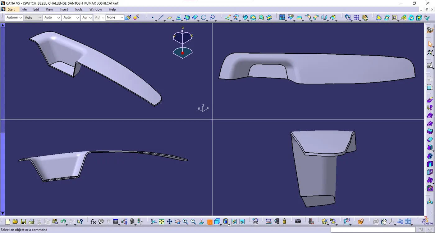
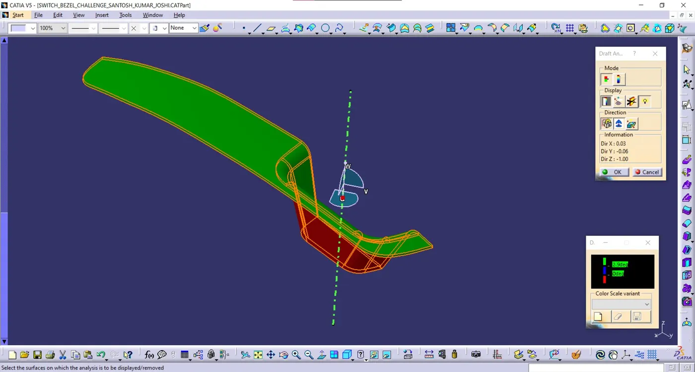
DRAFT ANALYSIS FOR FINAL PLASTIC PRODUCT:
Go to insert< analysis>
Align the tooling axis with the compass.
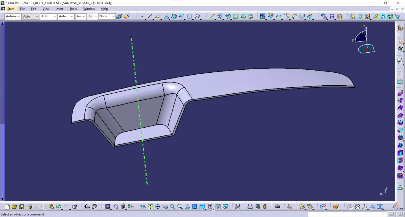
Click on the surface and see that the surface is within the permissible limits of draft values.
The upper surface should be green and the lower surface should be red and appropriate value (3°) should be entered in the column. But here I provide draft 2.9 degrees.
HERE BELOW ON IMAGE ISOMETRIC, TOP, SIDE AND FRONT VIEWS IS IT.
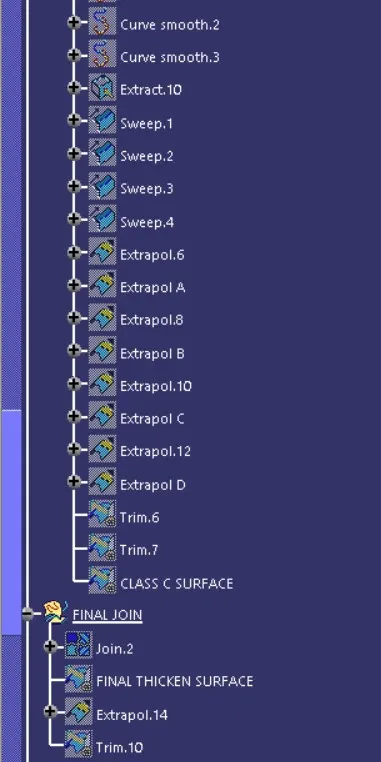
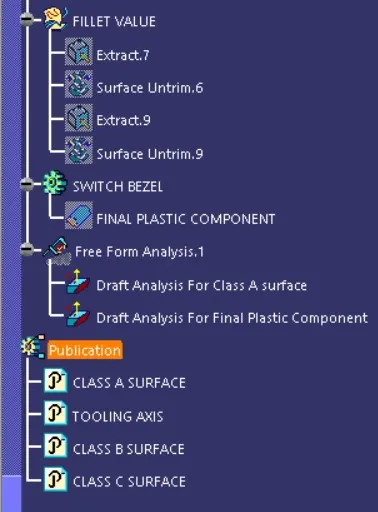
TREE STRUCTURE:
RESULT:
Switch Bezel plastic component using class-A surface successfully created and performed the draft analysis on the class-A surface and final plastic component.