Week 9 - Challenge 3 - Bumper
AIM : To Create the Bumper Plastic component through the given Class-A surface by taking the thickness of the component to be 3mm .
- A detailed report should be done explaining the draft analysis and the tooling axis creation.
1) Creation of Tooling Axis
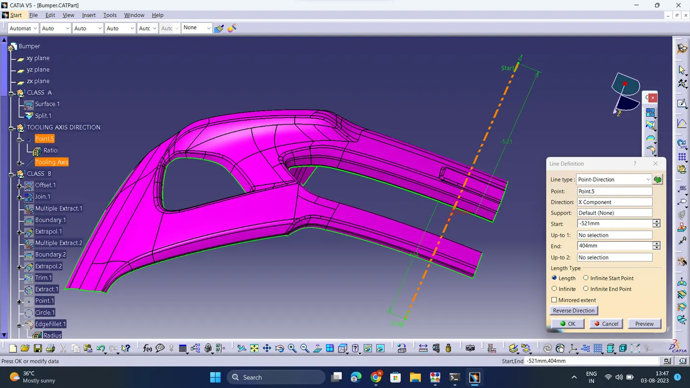
Tooling axis is the direction in which a core or cavity of mold opens. This Axis is very important to determine the orientation of the component in mold, core and cavity design.
For the creation of Tooling axis we need to check the class A surface in all the directions to find out the best direction to create Tooling Axis .
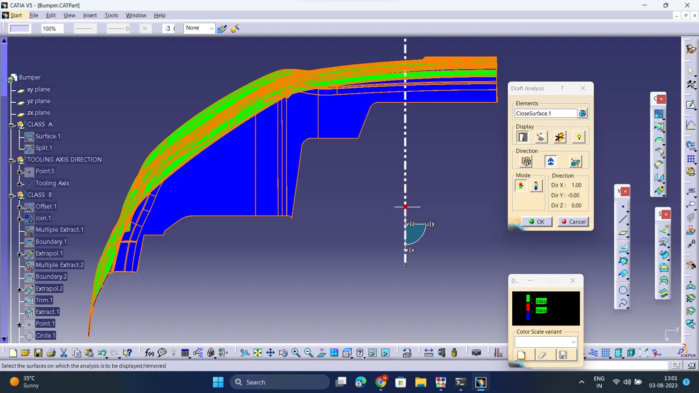
- In X direction
It clears most of the part in X dirextion
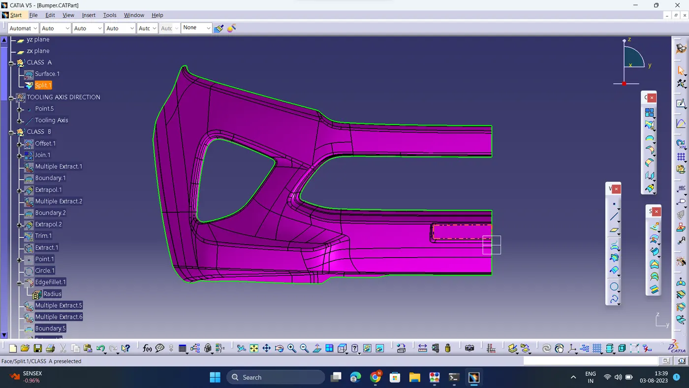
- In Y direction
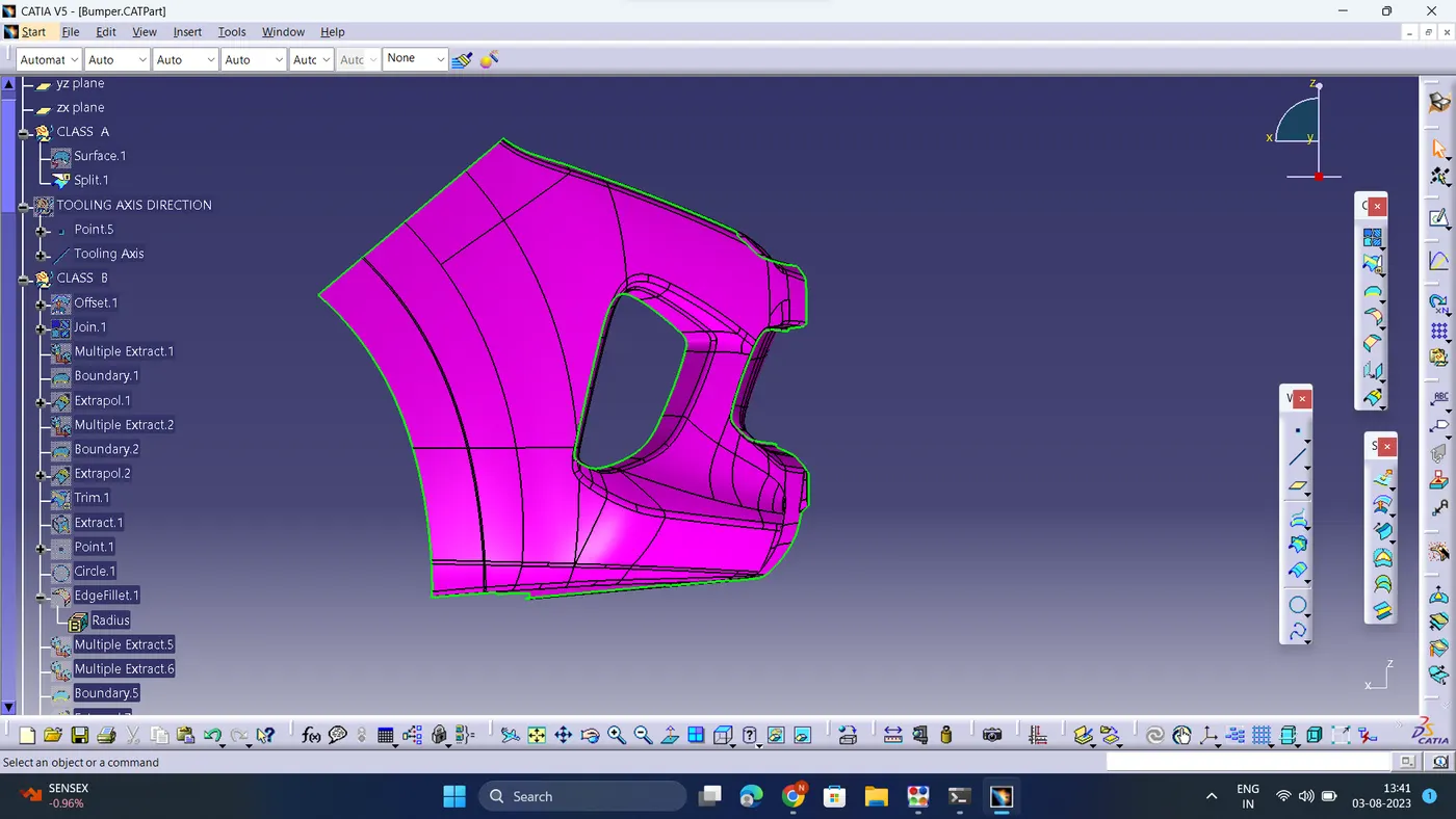
- In Z direction
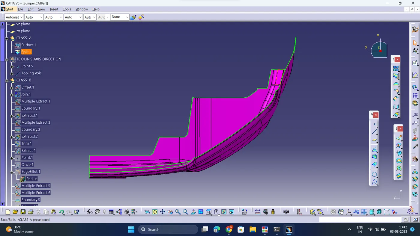
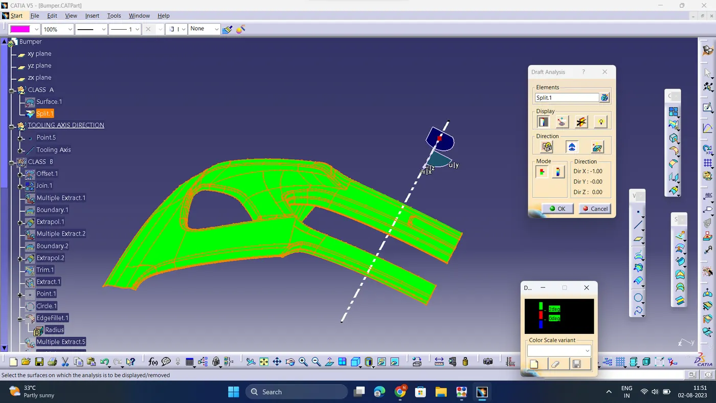
Among All direction , The X direction is the best direction to create the Tooling Axis
- First create a POINT on the surface of the part as shown
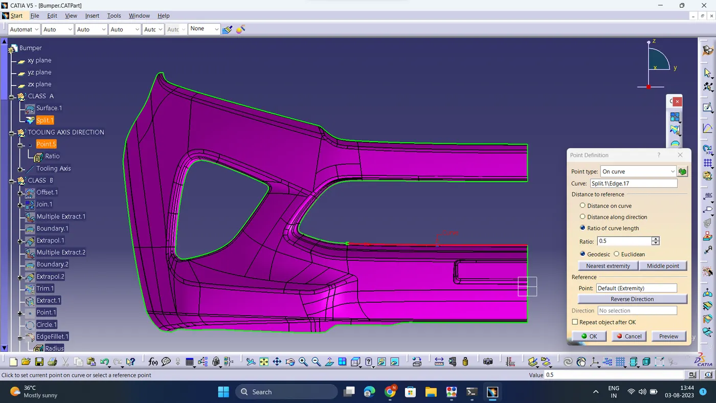
- Now Create a LINE using " Point-Direction " option and select point and X axis as the direction . This is our required Tooling Axis .
2) DRAFT ANALYSIS
No parts can be ejected from the tool if it is having a straight 90 degree profile from its base surface. A small draft angle is provided to each and every area of the component in order to get an easy removal of the component from the tool. Draft analysis technique is used to analyze whether our part model created in cad is manufacturable based on the draft condition applied. Here the part should get easily removed from the panel dies (in case of Sheet metal part) or Mold (in case of plastic). Here we are providing a direction in which components should eject inorder to get an easy removal of components from the tool. In other words it also lets us know whether the model is having a draft angle and how much is the draft angle from the tool direction.
Draft analysis is performed on the components where the ejection of materials happens after the material is made inside the tools. In case of Automotive Sheet Metal manufacturing, the blank sheet after turning into automotive panels like Hood, Fender, Roof, Side Doors, Back Doors etc, need to be removed from Panel Dies. If a considerable amount of draft angle is not provided, the removal components from the tool will be difficult. Same in the case of mold(plastic component) after getting filled inside the core and cavity, it needs to get ejected easily with the help of ejectors.
The major consideration of Draft Analysis is whether sufficient Draft Angle is provided on the component or not . Components while designing should be provided with a considerable amount of draft angle depending on the manufacturing consideration. For Plastic components we provide a draft angle of 3degree(Draft angle of 0.5 is given ideally to the features inside the plastic part). But for Automotive Sheet Metal Parts, it will be from 7 degrees or more.
Procedure to Perform Draft Analysis
i) First,ensure that to Change the view mode to Customize View Parameters and select " Material " option from the Mesh.
ii)Now Go to Insert --------> Analysis----- > Draft Analysis
Draft Analysis dialog box with colour scale (with quick analysis mode) appears on the screen. So the first mode option is the quick analysis mode and second is full analysis mode.
Here the quick analysis mode is used.
iii)Now,click on the component first by selecting the compass icon from the direction of the Draft Analysis dialog box. Compass may get misplaced from its original position after clicking on the compass icon. So Select the compass again place it over Tooling Axis one more time .
iv)Now Activate the compass and place the compass again on Tooling Axis and then click on the component .
v)Now th appearance of the part changes
To get a clear picture, either we need to adjust the compass by holding the marked region of compass and dragging it towards the opposite direction or by selecting the " inverses draft direction option " inside the direction of Draft Analysis
vi)After getting green colour on the component, try to adjust the compass using the knob, and adjust the direction of the compass to get green on the entire top panel region.
vii)Now Try zoom in and check if each and every region of the panel is showing green, if in some region, red or blue is showing instead of green, those negative regions are below 7 degree and have no draft applied on those regions. Those blue and red negative regions need to be changed.
viii) If we are ok with the result, right click on the compass and lock its current position using lock current orientation.
- Screenshots of the Draft analysis report for both the given Class-A surface and the final plastic component
1)Draft Analysis Of Class A Surface :
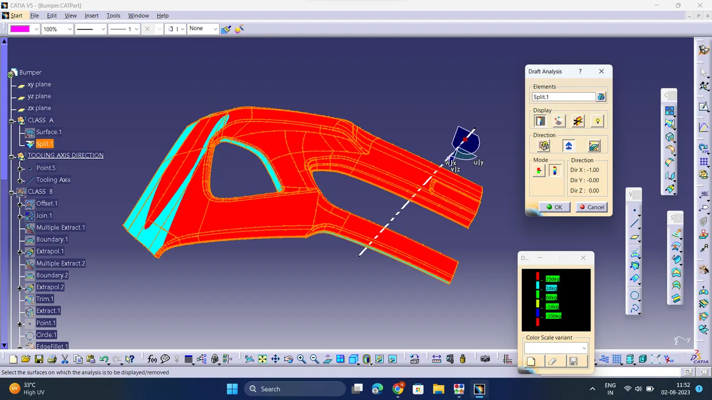
2)Draft Analysis of Final Component :
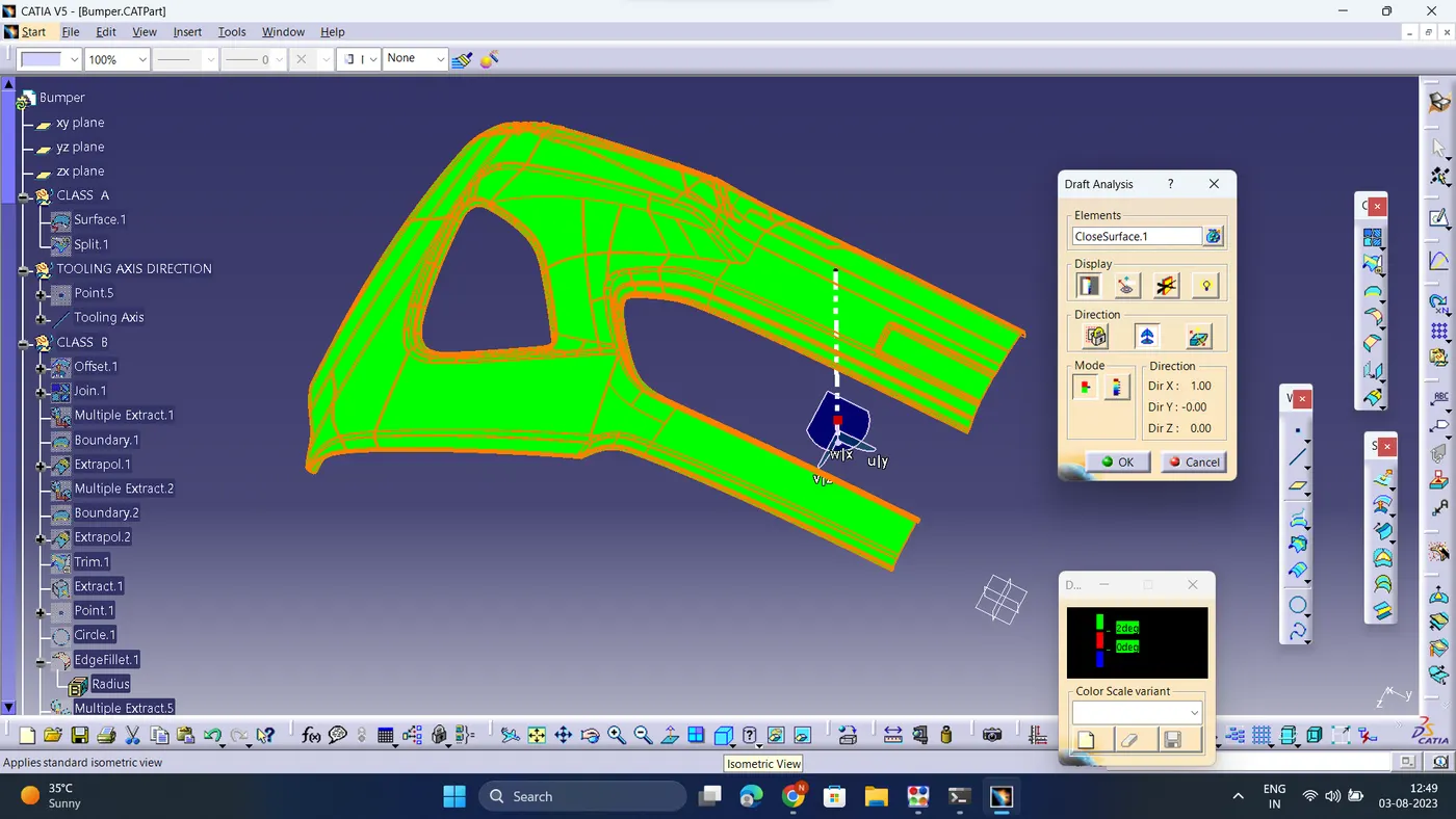
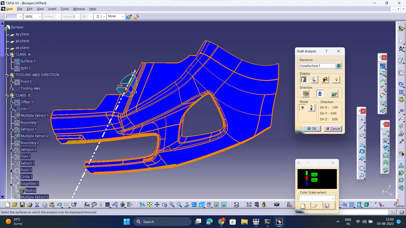
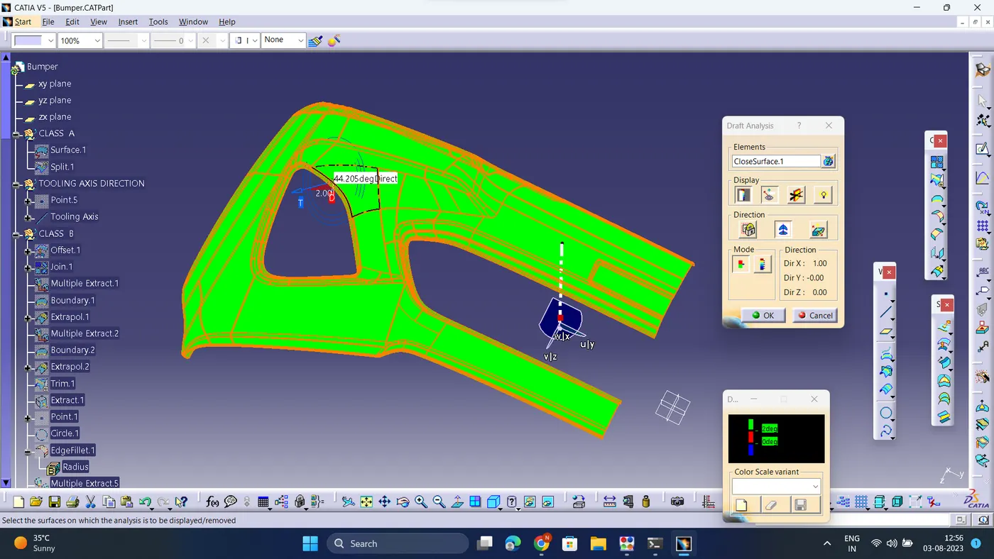
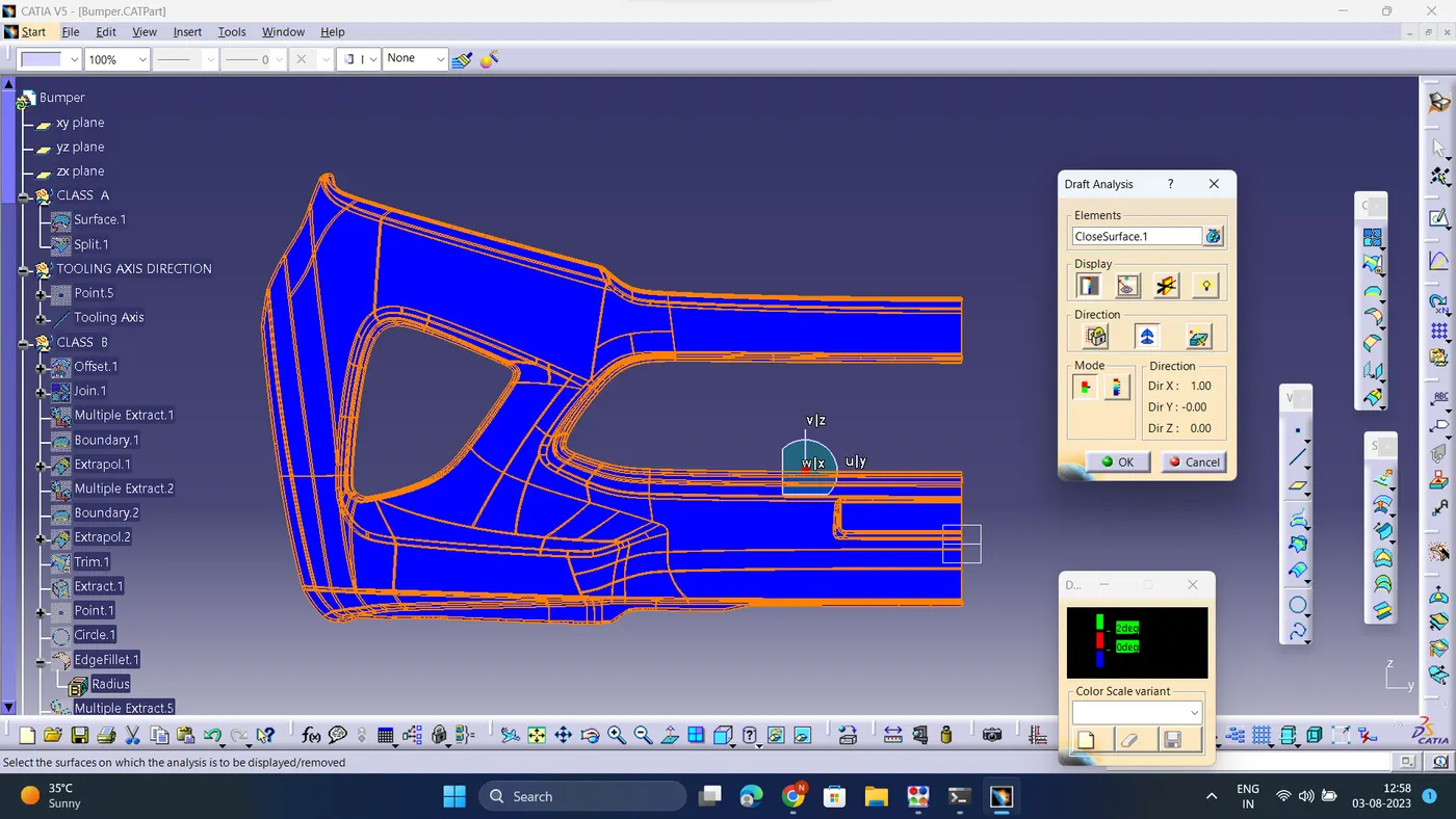
- Screenshots of the Solid model with the proper color code of the draft angle in various orientations (Isometric, Front, Side, and Top View)
The ideal draft angle for the plastic components is 3 degrees. This may vary according to the functional requirement. Apart from the draft angle consideration, remaining procedures for the draft analysis are similar to the above mentioned steps. The draft angle provided for the plastic features is 0.5 degree. This may also get varied accordingly.
1)ISOMETRIC VIEW
2)FRONT VIEW
3)SIDE VIEW
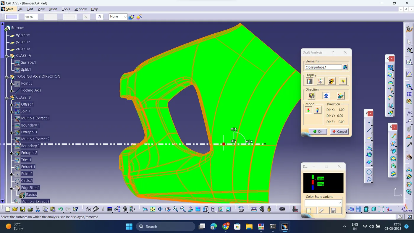
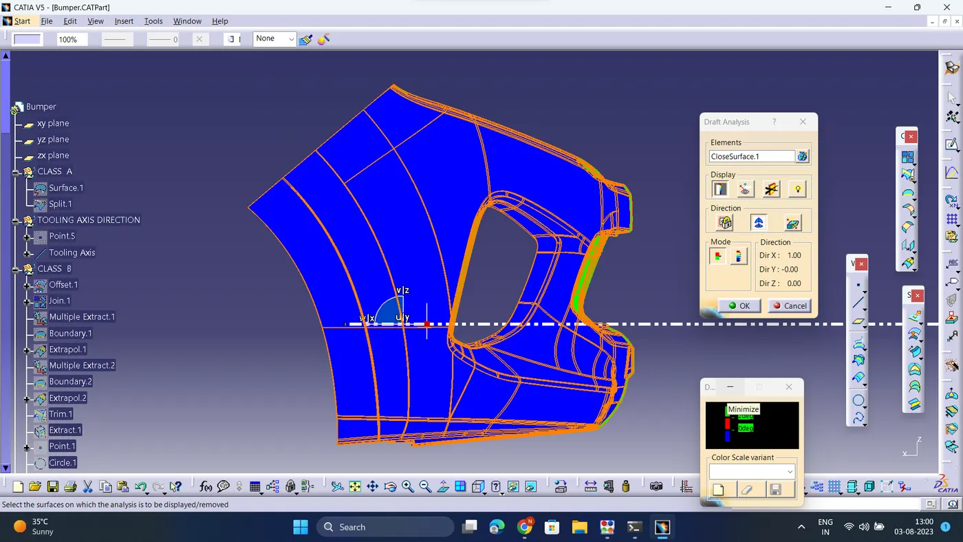
4)TOP VIEW