Week 9 - Challenge 3 - Bumper
AIM:
Create the Bumper Plastic component through the given Class-A surface. To begin with, the tooling axis for the given Class-A Surface should be created meeting the requirements of the draft angle and at the end perform the Draft analysis on the model.
Take the Thickness of the component to be 3 mm
INTRODCTION:
CLASS A:
Class 'A' surfaces are primarily used in the automotive environment and refer to those surfaces which are visible in a product. In other words: A - class surfaces are those aesthetic/free-form surfaces, which are visible to us (interior/exterior), and have an optimal aesthetic shape and high surface quality.
CLASS B:
Class B is a reference surface that is created by the design engineer and is a copy of the class A surface that is at a distance equal to the thickness of the part.
CLASS C:
Class C is again a reference surface that is created by the design engineer to connect Class A and Class B surface also known as the side wall of the surface
INPUT :
-
A-Surface
-
Thickness 3.00mm
- Draft angle - 3 degrees.
PROCEDURE:
In this model following steps are needed:
Tooling axis
Draft analysis
Class-B surface
Class-C surface
Making a solid model from surface.
Following commands were used to get final outpt:
Extract
Un-trim
Trim
Extrapolate
Offset
Edge fillet
Boundary
Sweep
Join
Close (part design)
GIVEN CLASS A SURFACE:
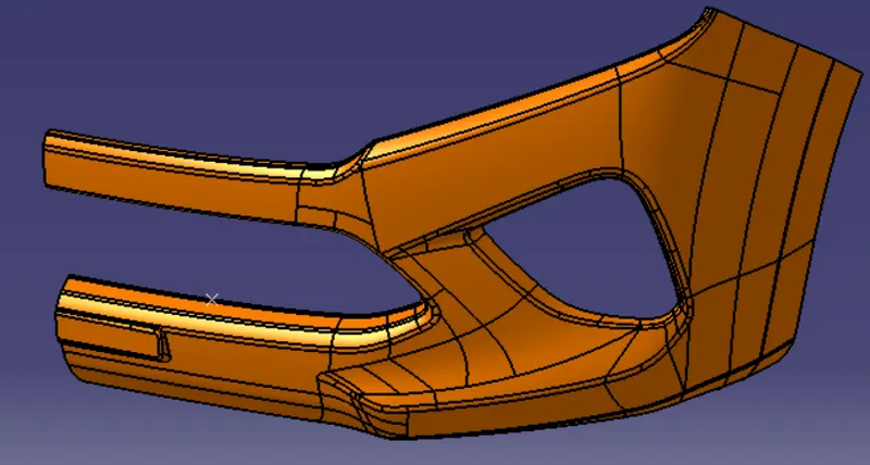
The above is the given class A surface.
STEP 1: CREATION OF TOOLING AXIS
Tooling axis: The direction in which the mold or core and cavity opens is the tooling axis.
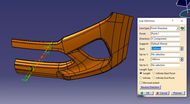
Tooling axis line is created on the point where it clears all the surface when put normal to in tooling line as we shown in below figure.
The point is created by measuring inertia,here the line along X-Axis is the tooling axis, in x-axis it is clearing all the surface.
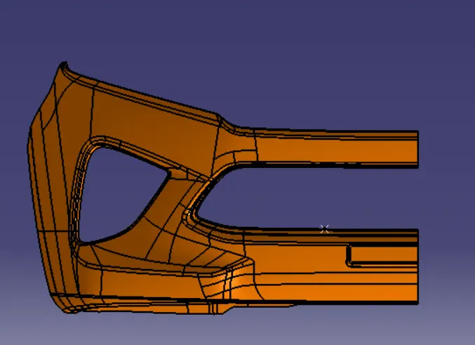
STEP 2: CLASS A SURFACE
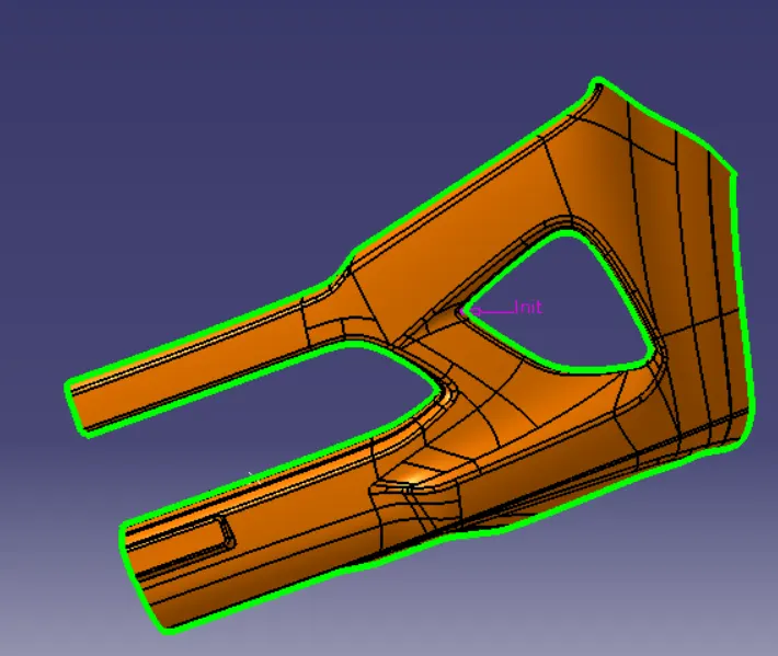
The A surface is checked whether it is without patches, using the boundary command.
STEP 3: CLASS B SURFACE
The B surface is created using the offset command here.
Offset distance = 3mm
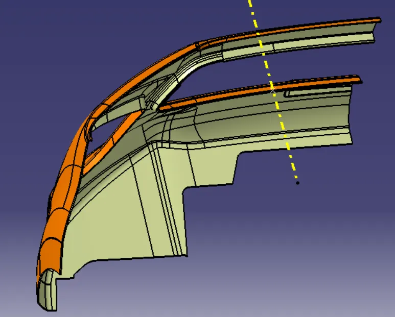
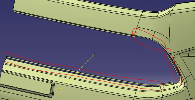
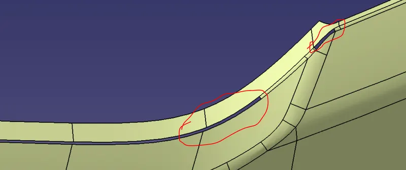
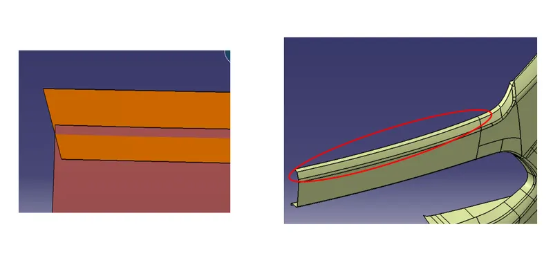
The offseted surface has some patches, that has to cleared to get the final B surface.
The patches are shown in below figures.
STEP 4: REMOVING PATCHES TO CREATE THE B SURFACE
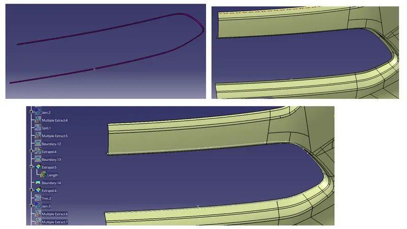
The surfaces need to be connected without patches are selected,extracted and extrapolate as shown below.
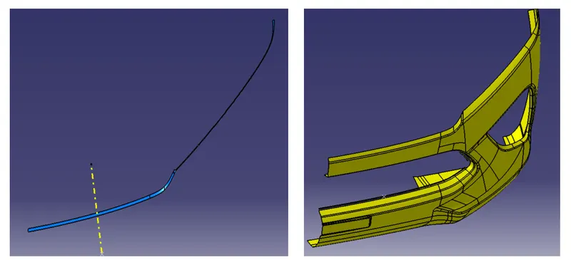
The extrapolated surfaces are trimmed to get the final surface highlighted as shown in figure,then the appropriate fillet need to be given.
Another patches are removed using the same method of extract using boundary,extrapolate the edges to connect two surfaces and trim to get the final surfaces and fillet it.
The above figure shows the B surface with removed patches.
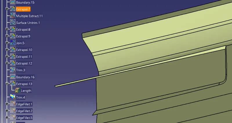
Patch removal of other surface:
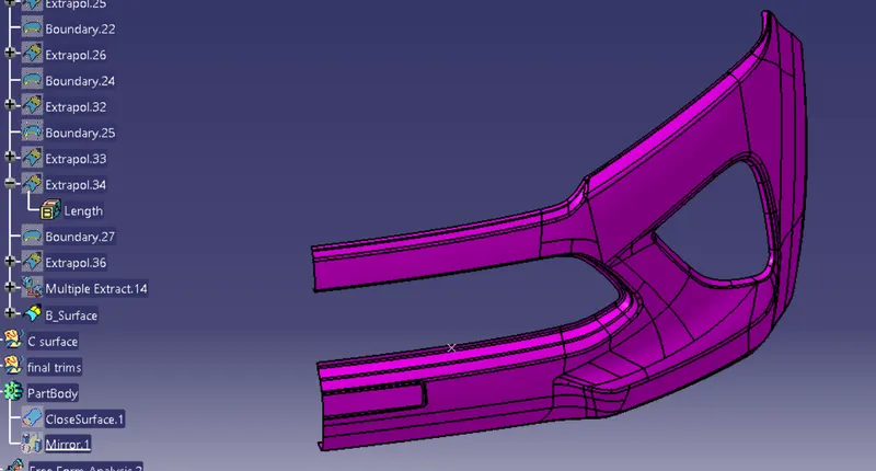
FINAL B SURFACE:
STEP 5: CLASS C SURFACE
The C surface is created using the boundary and Sweep commands.
The surfaces which is perpendicular to the tooling axis is sweeped along 90 degrees and
surfaces which is parallel to the tooling axis is sweeped with 3 degrees draft outside along the draft tooling direction.
The sweep C surfaces are shown in below figure.
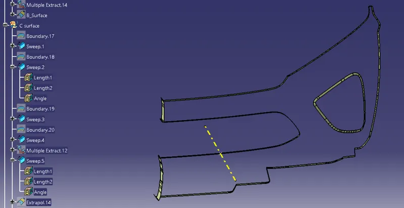
Joining of class A and class C:
The class A and Class C surface is joined and trimmed to get the final surface.
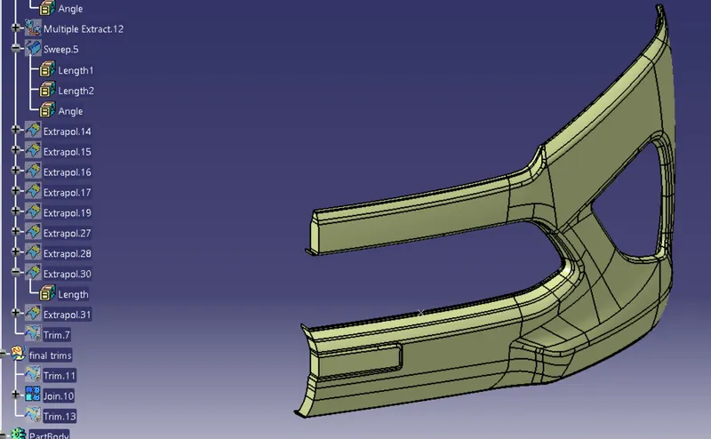
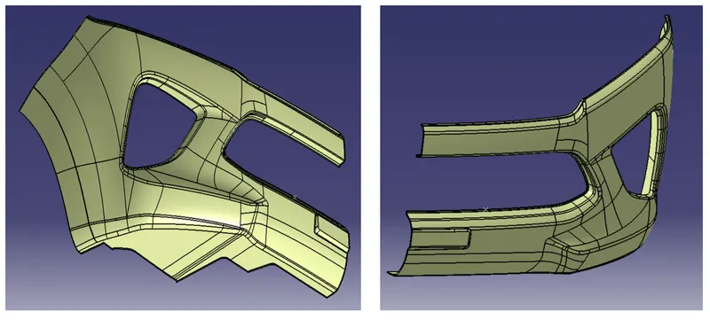
STEP 6: FINAL TRIMS
The trimmed A and C surface is joined with the B surface and again trimmed to get the final Bumper Model Surface.
The final trimmed surface is shown in below figure.
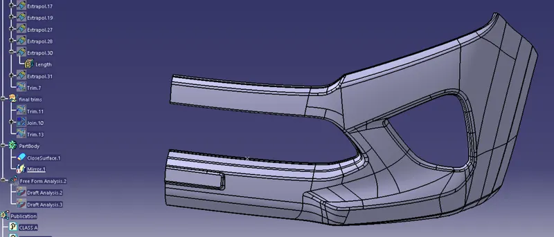
STEP 7: CLOSED SURFACE
After creating the joined surfaces,
Go to part Design > ClosedSurfaces >Select the final trim
STEP 8: DRAFT ANALYSIS
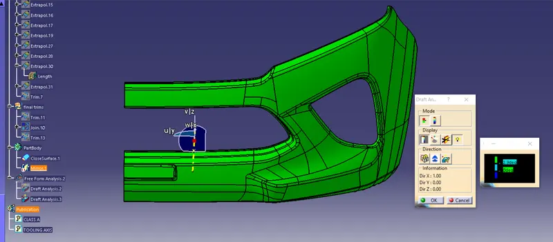
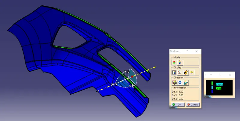
Finally draft analysis is done for the closed surface part,drag the compass to the tooling axis and touch the surface of the part to get the draft analysis result.
It shows the green colour all over the surfaces,It says that the part designed is able to manufacture and toolable.
FINAL BUMPER MODEL:
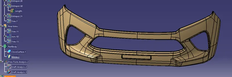
Mirror the closed surface to get the other half of the bumper.
CONCLUSION:
The Bumper model is created with thickness 3 mm using the given A surface by creating the Class B and Class C surfaces.Draft Analysis are done and the model is checked for Manufacturability.
The final model is attached with this report.