Week 9 - Challenge 3 - Bumper
Class A surface Boundary check
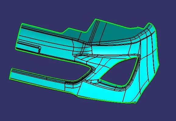
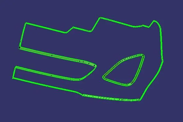
The styling surface, or A-surface, is first examined for any surface gaps and other problems. Since this Surface serves as the input surface, any corrections must be approved by the styling team or carried out by them. A boundary is constructed, the lines are only on the margins of a component and its holes or cutouts, creating a flawless surface, as seen below.
Tooling Axis
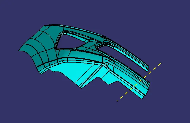
Determine the component's tooling axis. The opening of the cavity or the mould constitutes the tooling axis.
Look carefully to determine the ideal tooling axis.
Verify each axis.
The optimal tooling axis is x.
In this case, the bisecting method is not used as the line normal to the x-axis clears the draft analysis of all the faces.
Draft Analysis of Class A
B Surface
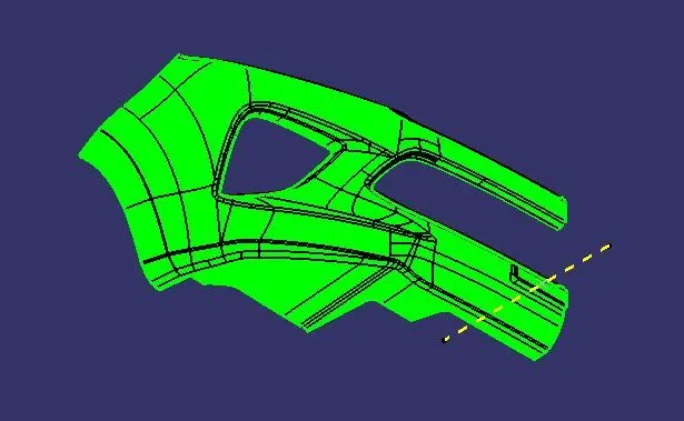
The A-surface is offset by 3.00mm since that is the necessary thickness.
Affected areas of the B-surface are closed using commands like Multi-section, Sweep, Offset, and Extract.
Ultimately, the offset surfaces formed previously are used to trim or unite all the created surfaces. The result was the creation of a single surface that will serve as the final B-surface.
By generating a complete border, a generated surface is examined for any holes or mistakes.
C Surface
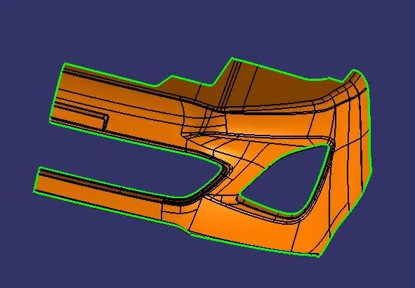
Another single surface, known as the C surface, connects the A and B surfaces.
With A surface serving as the reference surface and curve produced from the boundary of the same surface, it is made using sweep.
A-surfaces can also be produced by sweeping in a draft direction.
Draft Analysis of Closed Body
The draft analysis must be used to assess the final solid portion body. This is done to see if every part of the body meets the 3-degree draft angle requirement.
To help the part release from the mould, the vertical walls of the injection-moulded component include a taper called a draught angle.
Draft angles are a necessary component of bespoke injection-moulded products. Draft angles that face both the cavity and core sides are necessary for a functional injection-moulded item. This will lessen the possibility of the parts being harmed and make sure they can be removed from the machine.
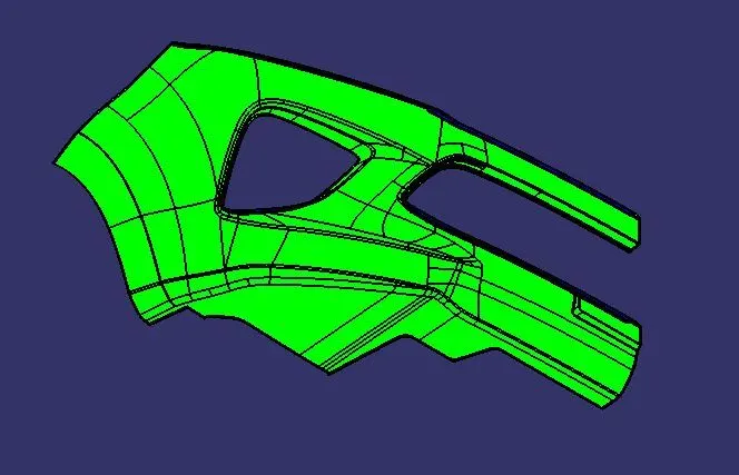
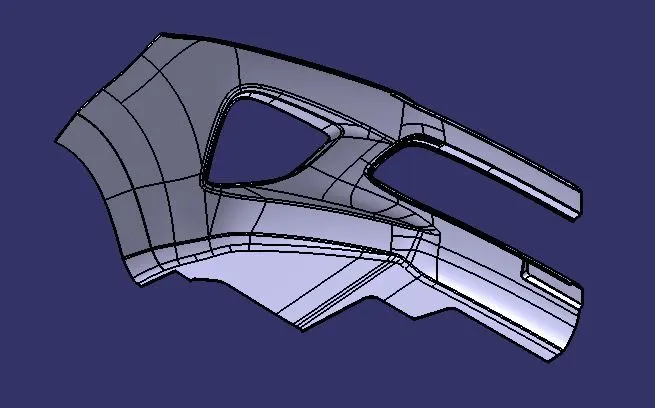
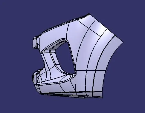
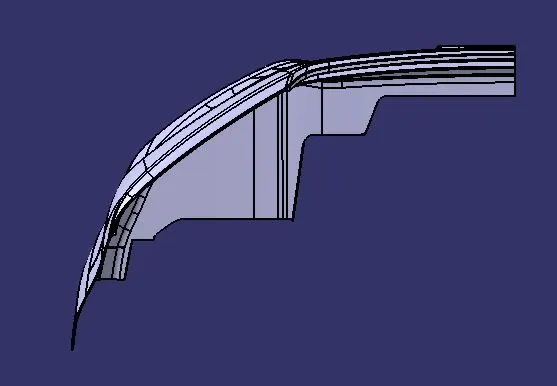
Various orientations of Closed body
Iso
Side
Front
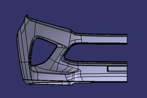
Top
Conclusion
As per the above challenge guidelines, a closed body is created by using Class A, Class B and Class C surface and draft analysis is carried out to analyse the release of component from the mould