Week 9 - Challenge 3 - Bumper
BUMBER:
Objective:
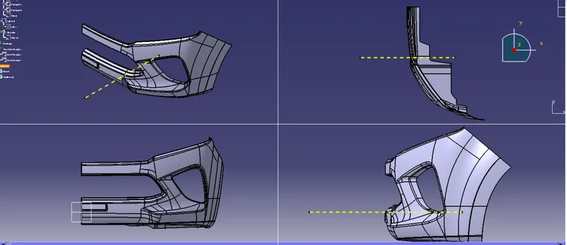
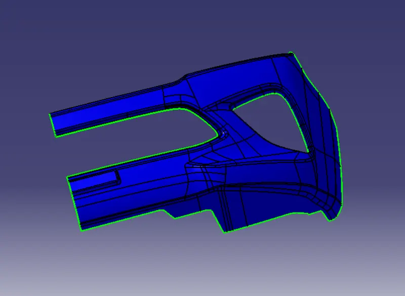
To create a Bumper solid component through a given Class-A surface.
Design procedure:
- Create a tooling axis on a class a surface and verify the draft analysis.
- To create a Class B & C surface.
- To create trimmed surface using created class A, C & B surface.
- Then use the trimmed surface to create a bumber solid component.
Tolling axis:
First check the given styling surface for any irreguler surface. Use the join command if an irreguler surface is found.
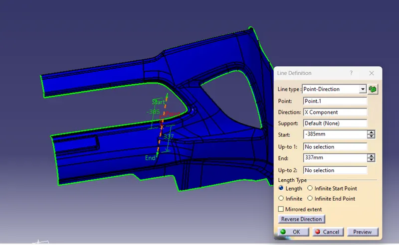
This surface has a different shape, so i used the point direction tooling axis.
Create a point on the given surface and then create a tooling axis using the line command in the point direction.
Draft analysis:
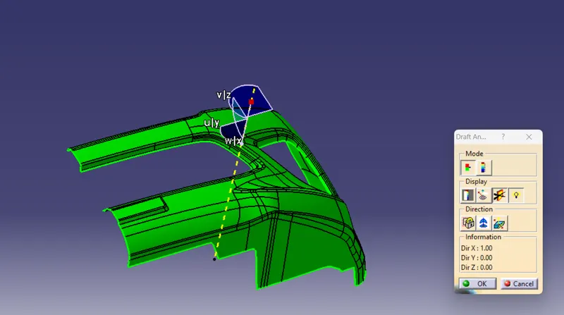
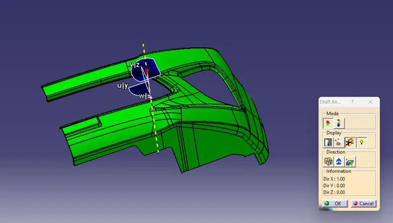
Draft analysis is done after determining the tooling axis on the Class-A surface, Draft analysis is used on the Class-A surface to check whether the minimum draft angle 3 degrees is maintained or not.
Given a surface angle of minimum 3 degerees, the whole component truns green. If the component truns green, Go to next operation.
Class B surface:
The Class-B surface is the secondary surface in the plastic component. Class B-Surface is extracted from the A-surface and it is offseted at 3mm in downward direction.
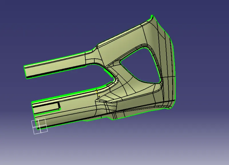
Some parts were missing from the created class b surface so i used extract ,extrapolate, offset, and trim commands to fix that.
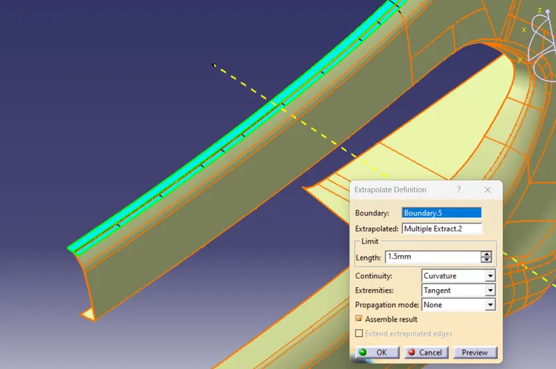
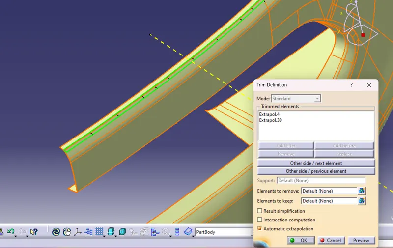
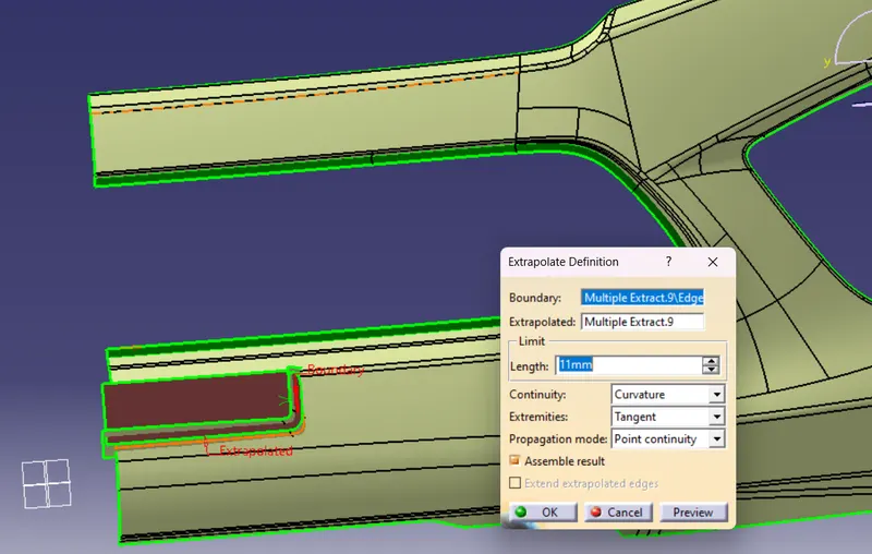
finally created a class B surace and then used the boundary command to check for any irreguler surface or gap, if there no defect, go to the next step.
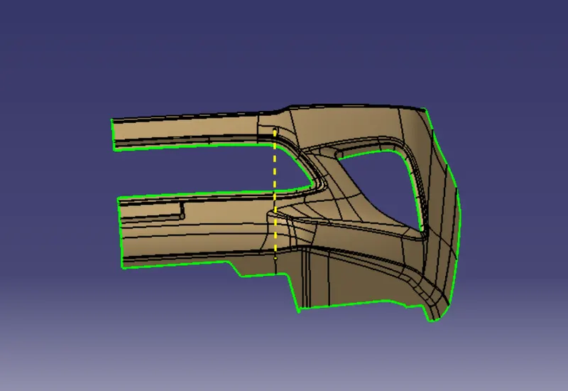
Class C surface:
The class C surface is the connecting surface. It combines class A and class B surfaces.
Create a class A outer boundary with the boundary command, then create a class C surface using the sweep command over the boundary.
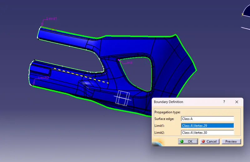
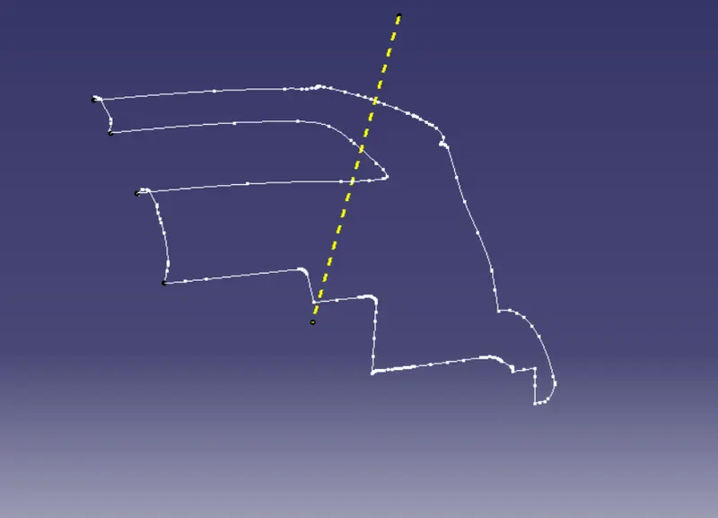
The class C surface is created by giving a minimum draft angle of 3mm in the sweep command.
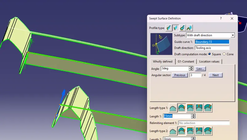
Trimmed surface;
Class A & B surfaces created using the trim command are joined to the required Class C surface.
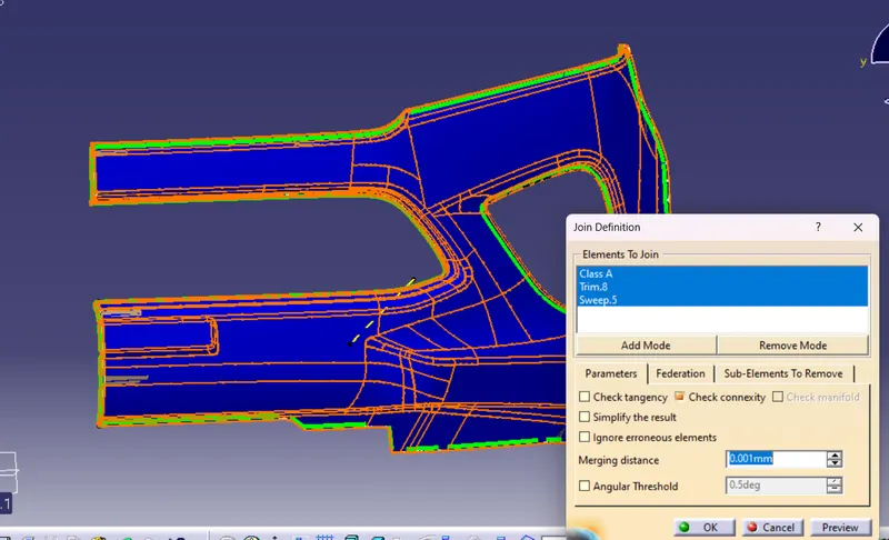
Finally got a trimmed surface.
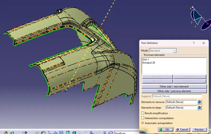
To check the trim surface created using the boundary command, if it does not get the boundary, got a closed surface.
Solid Part;
A solid part is created using the closed surface command on a trimmed surface.
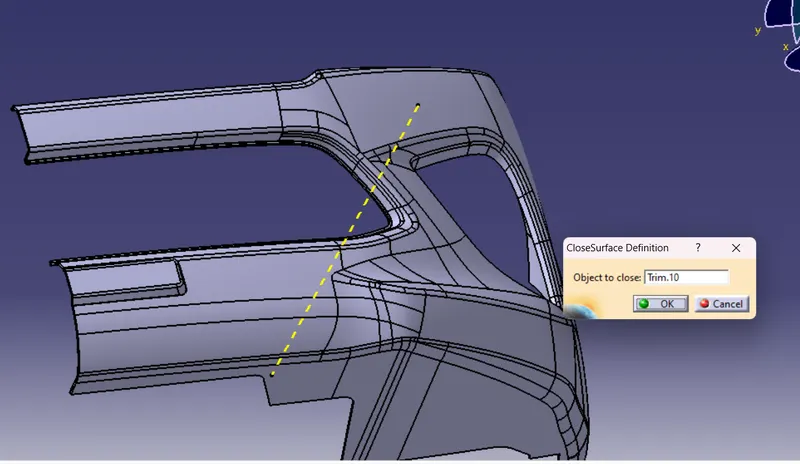
finally the solid part draft is checked to meet the production requirement through draft analysis.
Isometric, Front, Side, and Top View: