Week 9 - Challenge 3 - Bumper
REPORT ON BUMPER DESIGN
- Tooling Axis Creation:
- Class-A Surface from X-Direction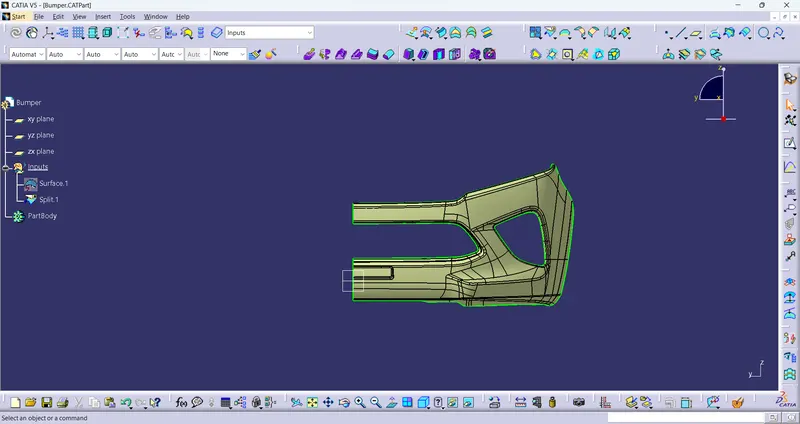
- Class-A Surface from Y-Direction
- Class-A Surface from Z-Direction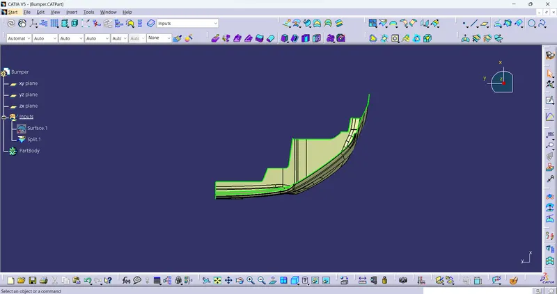
Visual inspection of the component from each direction shows that all the surface patches are clearly visible from the X-Direction and it is therefore ideal for the Tooling Axis. Since, if all the surfaces are visible from one direction then they can all be tooled from that direction. We find that from X-Direction we can avoid using any overhangs or side cores.
Unlike the earlier exercise, we cannot create the Tooling Axis using bisecting lines due to the complexity of the surface. Instead, we create a Dummy Tooling Axis in the direction we deem appropriate and use Draft Analysis to check if the surface can be cleared in that direction, If we find some surface patches that cannot be cleared, we can then adjust the Tooling Axis.
- We create a point on any curve (preferably somewhere in the middle of the surface) and use that point to create a dummy tooling axis in the X-direction.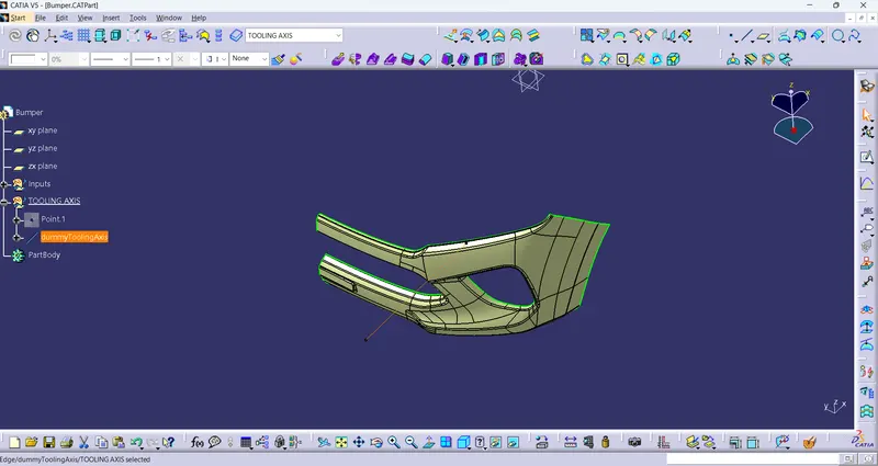
- Now, we perform Draft Analysis to see if the Class-A surface clears the Tooling Axis.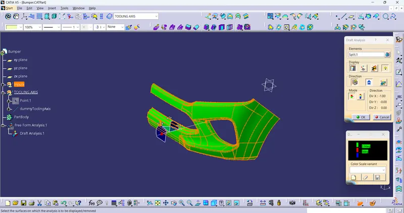
From the above image, it is clear that all the surface patches have an angle of 3 degrees or above with respect to the Tooling Axis and can therefore be easily ejected from the mould in that direction.
As a result, we can confirm that the Tooling Axis we created is usable and change the name appropriately.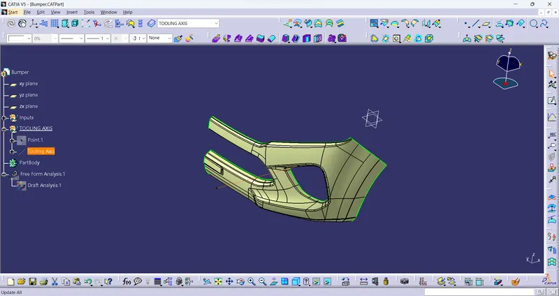
- Draft Analysis:
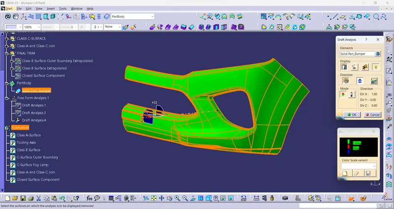
- Performing the Draft Analysis on the Class-A Surface shows that all the faces have required draft angles with respect to the tooling axis and therefore can be easily ejected from the mould.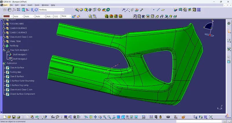
- We perform the Draft Analysis on the Closed plastic surface to make sure that the B-Surface and the C-Surface we created also have the required draft angle.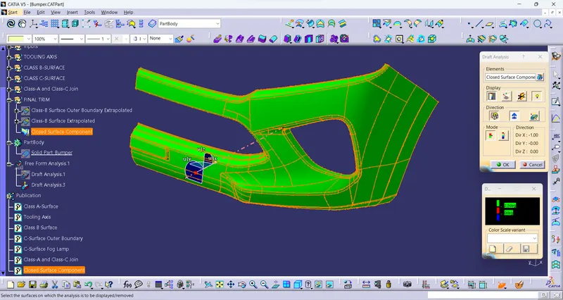
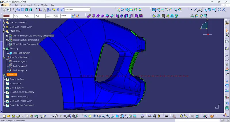
The only surfaces we have provided a 3-degree draft angle are the C-surfaces for the edges that lie on the ZX plane and the inner edge of the radiator grill. We, therefore, have to make sure that those surfaces can be cleared in the Tooling Axis.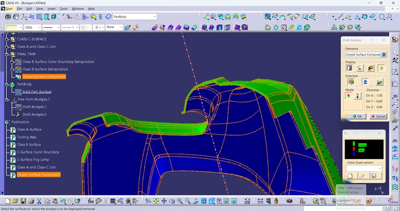
From the above image, we can see that the surfaces are "Green", proving that the Draft Angle provided is 3 degrees.
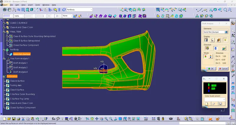
- Finally, we perform Draft Analysis on the solid Plastic Product.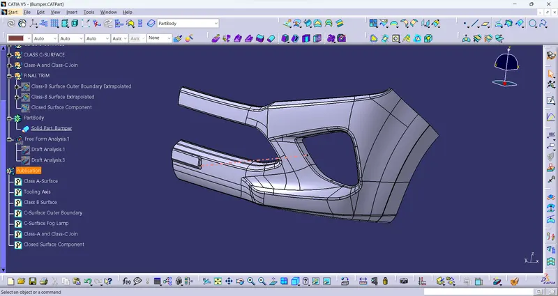
- Isometric View: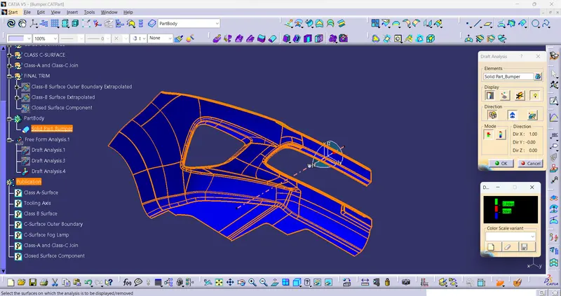
- Front View: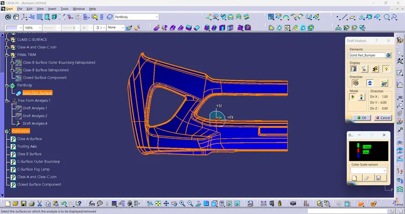
-Back View:
- Top View: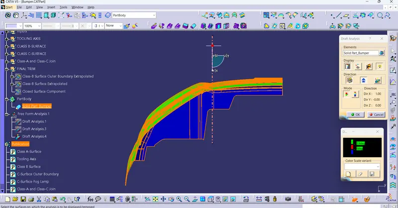
- Side View