Week 9 - Challenge 3 - Bumper
Aim: Create a tooling axis in a proper way for finding better draft analysis from a given class A surface. Create a draft analysis of the class A surface and create a class B and class C surface from the class A surface. And finally, create a draft analysis of the finished body. Consider the thickness of the component 3 mm.
CLASS A: The top (which is given) surface of the component is called a class A surface.
CLASS B: The bottom surface of the component is called as class B surface.
CLASS C: The surface which is connecting CLASS A & CLASS B surfaces is called as class c surface.
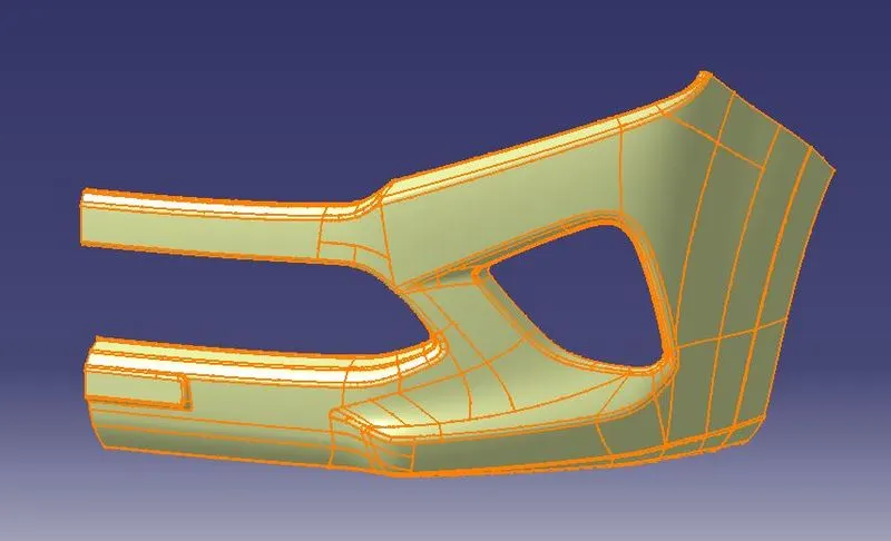
In automotive design applications Class A Surfaces are created on all visible exterior surfaces (ex; body panels, bumper, grill, lights, etc.) and all visible surfaces of see-touch & feel parts in the interior (ex: Dashboard, seats, door pads, etc.). This can also include beauty covers in the engine compartment, mud flaps, trunk panels, and carpeting. This surface has a 0 mm thickness.
Draft analysis: The draft analysis technique is used to analyze whether our part model created in CAD is manufacturable based on the draft condition applied. Here the part should get easily removed from the panel dies or Mold (in the case of plastic and sheet metal parts). No parts can be ejected from the tool if it is having a straight 90-degree profile from its base surface. A small draft angle is provided to each and every area of the component in order to get easy removal of the component from the tool. Here we are providing a direction in which components should eject in order to get easy removal of components from the tool. In other words, it also lets us know whether the model is having a draft angle and how much is the draft angle from the tool direction.
In this challenge tooling axis is created by the following method:
Normal To Surface method:
In this method extract one flat surface from the class A surface and create one point on the extracted surface. Create the dummy axis for tooling direction.
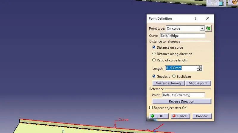
After creating of dummy axis, The Drafting analysis was performed using the Feature Draft Analysis command.
Using this command, the compass was set on the main tooling axis and the Draft angle was changed to 3 degrees.
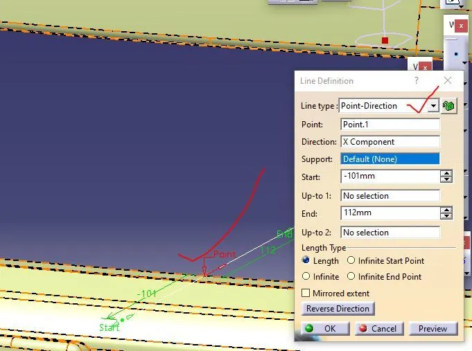
The tooling axis or tooling direction is the main consideration for plastic parts and mold parts because it defines the movement of the mold part and the possibility of the plastic part coming out from the mold part (Core and Cavity). In Molding, machine arrangement is given to open the mold along a direction which is known as Tooling Direction. The mold is built from two separate halves (Core and Cavity) and the tooling direction basically defines the direction of the mold pulling apart. Tooling direction is known as primary direction.
Here I have created a tooling axis. First of all, I extract a base surface and create a midpoint on it. And then I create a line through this point perpendicular to a base surface. And then I performed a draft analysis and I saw every thing is ok. Then finally it is my tooling axis.
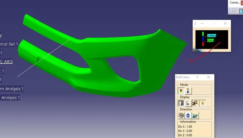
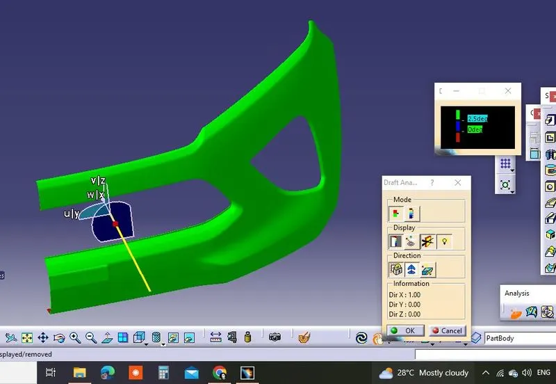
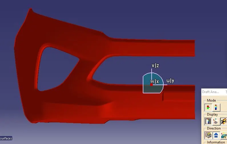
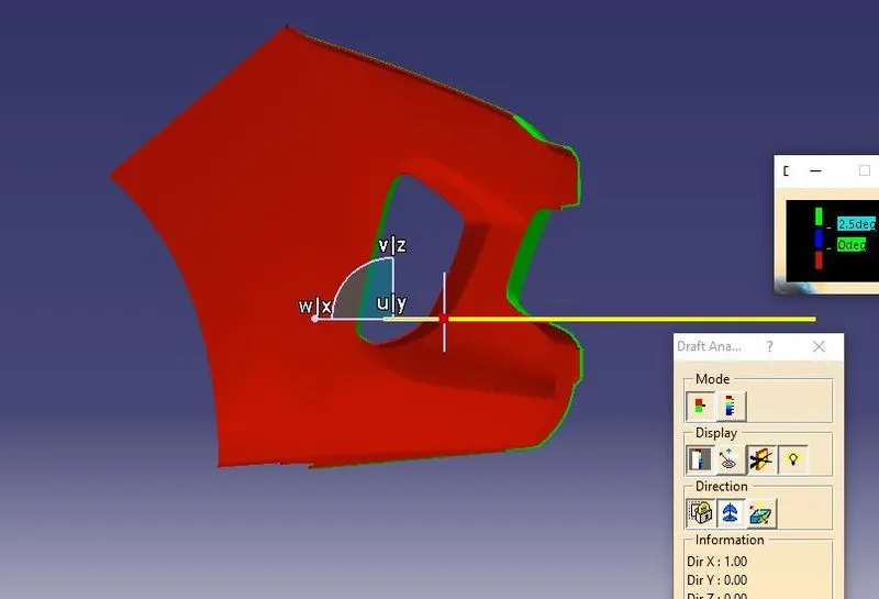
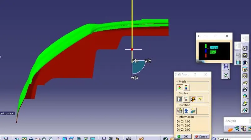
Draft Analysis of Class A Surface in CATIA provides color-based identification. With the help of this, we can easily find which surface is clear and which is in stock by color changing. Here I give the draft angle 3 degrees. The result in color based that the surface which is green (which means draft angle > 3 degrees) is right. And where the color is blue mean draft angle is 3 degrees to 0 degrees if this surface area is low then you can go. If you find a red color zone then it means the draft angle is less than 0 degrees. Then you will have to create the tooling axis in another way if possible, otherwise, you can say your design engineer to correct for design.
Creating Class B Surface:
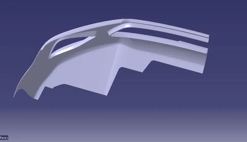
To create class B offset the class A surface of 3mm inside as per the given data. After offsetting the class A the class b surface creates some errors as follows:
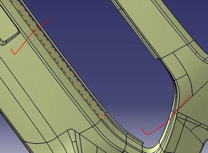
In the above picture, we can see clearly the fillets are not created fully. So, to make a good quality class B surface, the above surface further split and extrapolated the surface where the fillet is forming and trim those extra surfaces, and created the class B surface. The final class B surface is as follows:
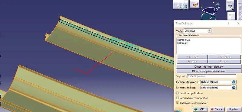
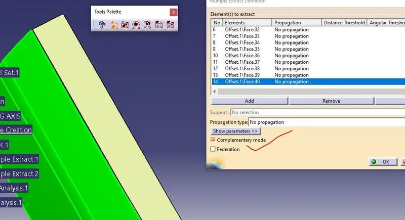
Creation Of Class B surface steps, Create a new Geometrical Set as a B surface creation. Offset the Class A surface by using Split Command to 3 mm. Using multiple extracts to extract the top surface. Use multiple extracts to remove the patches by using the complementary mode to select the opposite side. Unhide two multiple extracts that we created. Extrapolate both the multiple extracts by using the boundary and extrapolate commands. Use the trim command to trim both the extrapolated surfaces. Use proper length so that both the surface gets intersected properly. Use multiple extract and split commands to remove the bottom surfaces. Use other side in the split command to get separate output. Use the join command. Select trim 1 as Elements to join and select the option-sub elements to remove and select the elements that have to be removed. Extrapolate the surfaces we have created using the split command and the join command and trim them. Use proper length so that both the surface gets intersected properly. Similarly, check for other errors and fix them using the same extrapolate and trim command. Give fillets wherever needed.
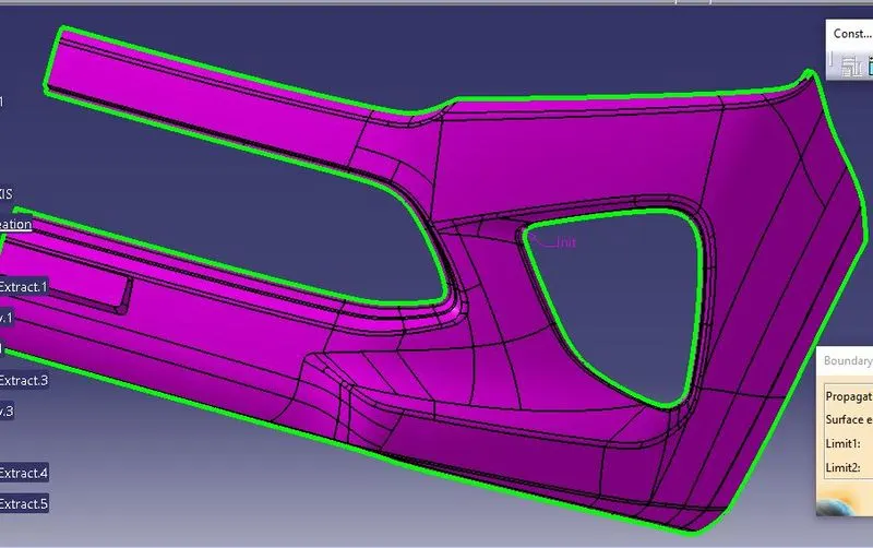
Creating Class C Surface: The Class C surface connects the Class A and Class B surfaces. Initially, the outline of the Class A surface was obtained using the Boundary. In this model there are two types of class C surfaces are there one is parallel to the draft axis and another is perpendicular to the draft(tooling)axis. The following edges are parallel to the tooling axis and the picture as follows:
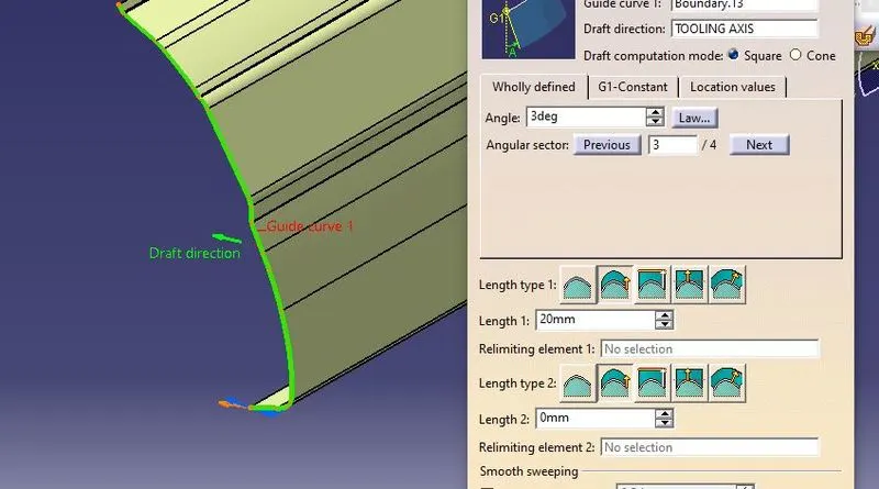
Split the surface with the parallel plane. Insert Geometrical Set. Rename it as B surface creation. Create a boundary on the class A surface for the sweep command. Sweep the boundary with the 3-degree draft. Similarly, sweep the right and left surfaces. Then sweep from left to right side to complete the boundary. Finally, sweep the center part. At last, intersect all the sweeps and trim them to get the final sweep. Insert another Geometrical set as A and C trim. Join the Class A surfaces with the sweeps that we have created. Insert geometrical set as final trim. Trim this Join surface with the B surface. Create this as a close surface in part workbench.
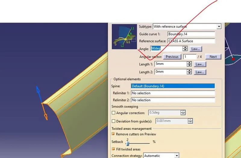
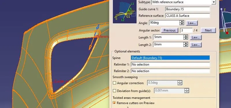
The Sweep command was used along with draft direction, with a draft angle of 3 degrees.
The final Class C surface looks as follows:
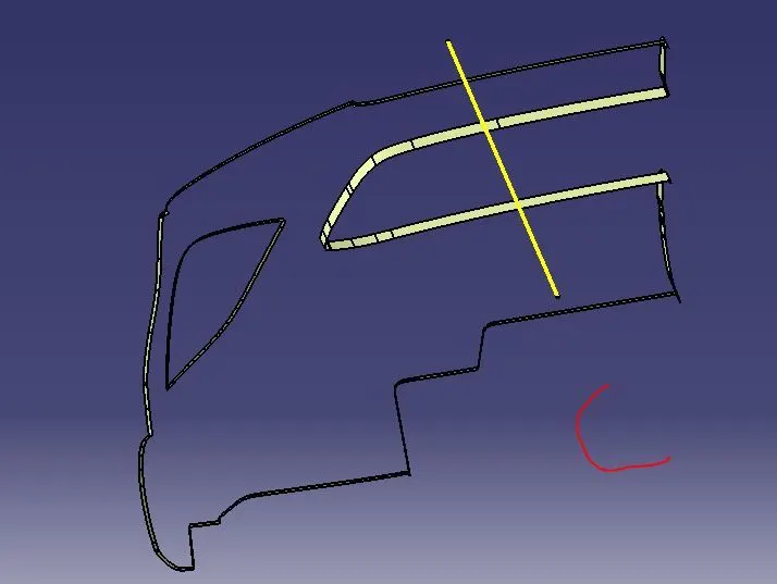
After the creation of Class C, we need to join A&C. Finally, all the 3 surfaces were trimmed to form a closed surface. (A, B, C Surfaces). The final trim forms a close surface.
After forming the closer surface check the surface with the boundary option.
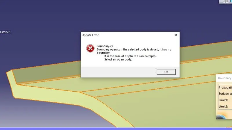
Because of the closer surface, the above error will appear. Now we shift to the part workbench to add the thickness to the model.
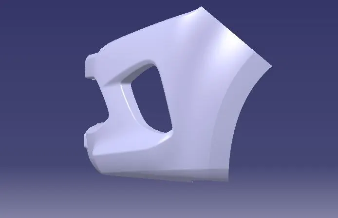
The final thick model
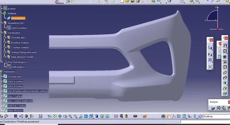
Draft Analysis:
The Draft Analysis allows the user to easily analyze a part for a proper draft angle. A Draft Angle describes the amount of taper for molded or cast parts perpendicular to the parting line. Draft Analysis is applicable for 3D part models. To create a draft analysis for any 3D part file, the user needs to select the part/surface and select the pull direction. You can change the pull direction.
Select the compass and place it in the tooling axis. Check if the area is cleared properly. The vertical component is clearing but the horizontal component is not clearing properly. So give a draft angle of 2.5 degrees instead of 2.9 degrees. We can now see that the desired surface is clearing properly. In this manner, we have created the Class A, B, and C surfaces and carried out the draft analysis on them.
Isometric, Front, Side, and Top View
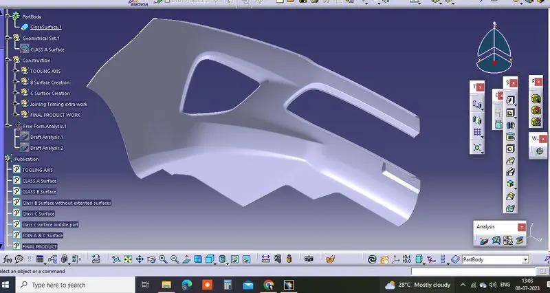
Conclusion:
In this project, we learned how to find the tooling axis in an appropriate way and how to create Class B and Class C Surface from Class A Surface. The Draft analysis of the component showed that the component is feasible to be molded without any issues. Thus it satisfies all design and manufacturing criteria needed for a proper part.
ZIP FILE:
https://drive.google.com/file/d/1M21F41BWGgl5ogm2tz13gKRj4LRNxuC2/view?usp=sharing