Week 9 - Challenge 3 - Bumper
AIM:
Create the bumper plastic component using the Class-A surface that is provided. The tooling axis for the specified Class-A Surface should be produced first, according to the demands of the Draft angle, and then the model should undergo a Draft analysis.
INTRODUCTION
A bumper is a structure that is incorporated or connected to the front and back ends of a car in order to reduce damage in the event of a small accident. They are intended to minimise damage from low-speed collisions and to absorb impact to the front and rear of automobiles. Today's typical passenger car bumpers feature pieces of compressible foam or plastic behind a hard reinforcement bar on the underside of the outer cover.
A bumper consists of the following four components:
- Bumper cover.
- The bumper absorber.
- The bumper reinforcement bar.
- The bumper mounting system.
The first automobile bumpers were built in 1901 and comprised of metal bars fastened to the front and rear of the vehicle to shield it from harm in the event of a slow-speed accident. Early metal bumpers prioritised sheer durability since they were made to shield pricey and delicate parts including the cooling system, hood, exhaust, and lighting systems. Modern consumer-produced automobile bumpers are now nearly exclusively made of plastic. Thermoplastic olefins, a mixture of plastic molecules, rubber, and a reinforcing filler like carbon fibre or calcium carbonate, are used to make modern automobile bumpers. This combination of components produces a scratch- and impact-resistant plastic that can adhere to a variety of paints and finishes, which makes it perfect for car bumpers.
There are various reasons why plastic is the material of choice for modern automobile bumpers. The primary benefit of plastic over metal is that it is both lighter and more aerodynamic, which increases the fuel economy of the vehicle. Additionally, plastic is simpler to mould, which is advantageous for both production and bumper repair.The majority of current cars have bumpers composed of PC/ABS, a material blend of polycarbonate (PC) and acrylonitrile butadiene styrene (ABS).
OBJECTIVE
- To create a bumper that adheres to standards set by the car industry.
- For the provided CLASS-A surface, create tooling axes.
- Create surfaces of classes B and C.
- Using the close surface command in the component design workbench, create the final surface model and turn it into a solid body.
- Analyse the Draft anayisis for the Class-A surface and the final part body.
DESIGN METHODOLOGY
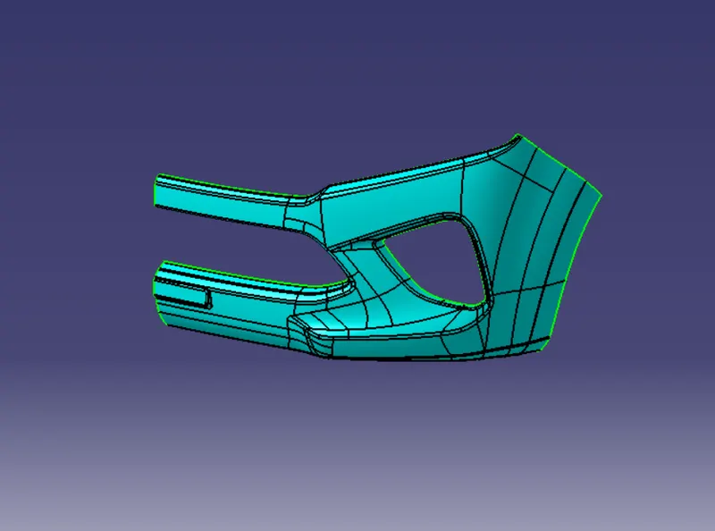
The style team would provide us access to skin data. Visible surface is a Class-A surface. It provides the style team's look for the component, which the part design engineer uses to develop the component with all of the engineering requirements. The class A surface's continuity must be verified first. In order to prevent gaps between surfaces, this is done. If any, we should address them right away.
Check for Class-A continuity Visually observe the class A surface to analyse it.
to ensure that there is no space between them on the provided surface. With the use of the Join or boundary commands, we can additionally verify it.
Procedure for creating Tooling Axis:
When the components are manufactured, the opening and shutting of the mould cavity and core is represented by the tooling axis. The optimal tooling direction should be taken into account by a plastic product designer in order to drastically reduce component costs.
Method chosen to create the tooling axis for the bumper
- Verify which tooling direction will work best on the given surface.
- By comparing all three axes, we can determine the ideal tooling direction.
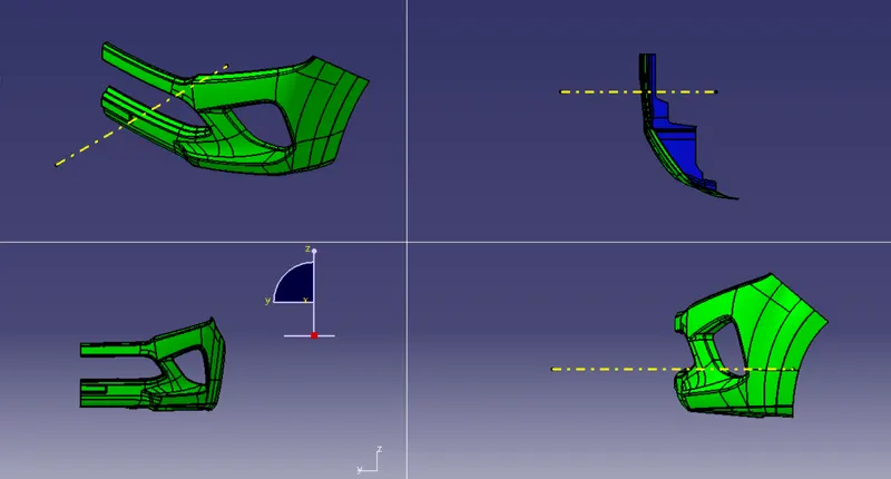
- The optimal tooling direction for the pumper class may be found here.There is a surface in the x-axis direction.
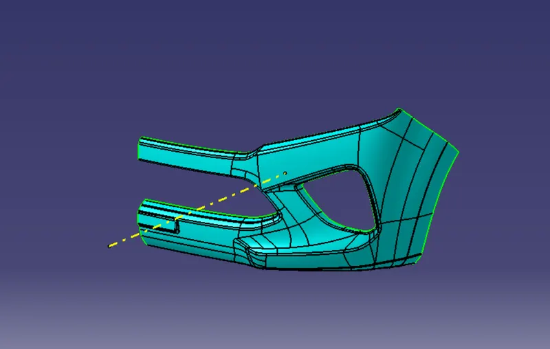
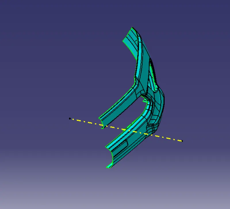
In order to generate the tooling axis, first remove a surface and then draw a midpoint on it. On that point, they established an axis system. - Following that, a was formed with the location and direction along the x axis.
Here, the Draft between the two outer flanges and the formed axis is 5.1 degrees. Therefore, following the generated axis will not cause any problems during the Draft analysis.
Making intersections in the y direction is another technique. Next, draw lines on the walls, and using the lines on the walls and the earlier-created point, draw a bisecting line. We shall obtain an axis that satisfies the demands of the Draft analysis.
Draft analysis for the given CLASS-A surface:
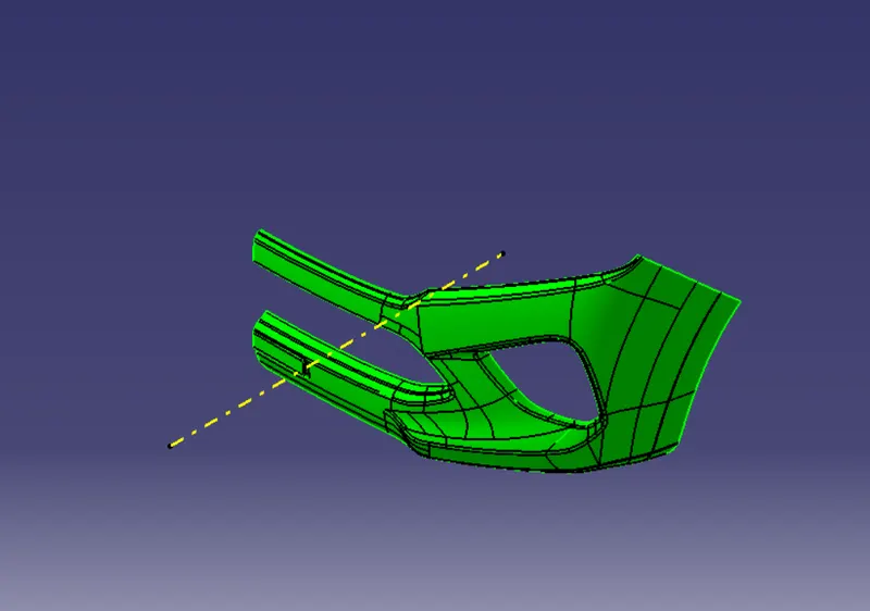
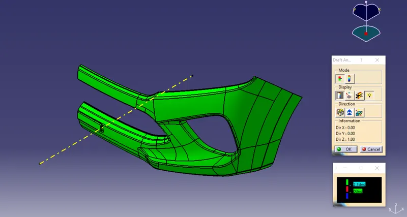
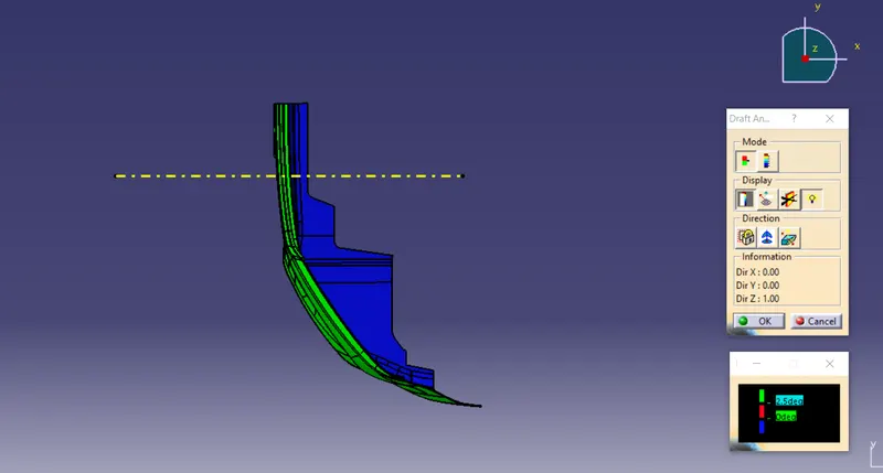
You may use the Draft Analysis command to see if the section you drew will be simple to delete. This kind of analysis is carried out using color-coded zones on the studied element that correspond to certain values when the deviation from the Draft direction is present at any location.After choosing the tooling axis, Draft analysis is carried out to see if the minimal Draft (3 degrees) is being maintained.
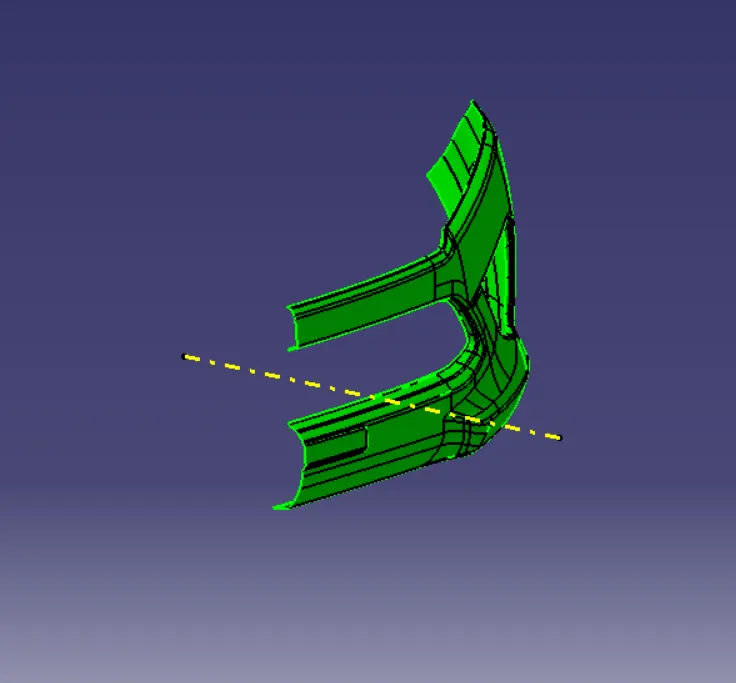
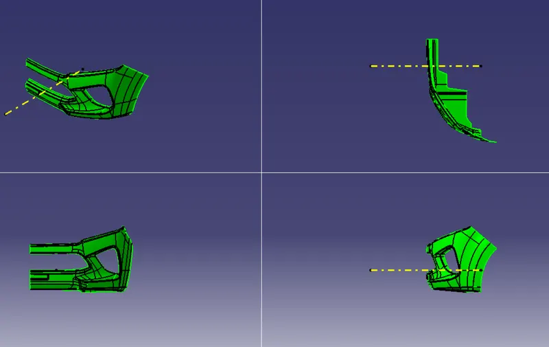
Creation of B SURFACE:
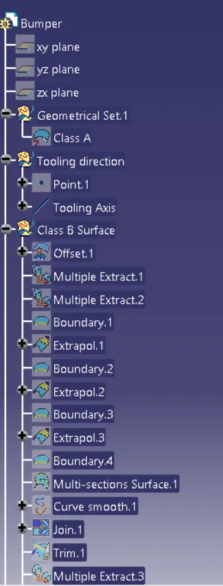
Class-B surface refers to a part's thickness that is both inside the component and not visible. To put it another way, a Class-B surface is one that is thinner than a Class-A surface. This is the area of a model where the engineering components are located. Set the class-A surface 3 mm to the inside.
Using features such as extract, multi-extract, sweep, multi-section surfaces, and extrapolate, rework the patches and discontinuities of the offset surfaces. Check the boundary command to determine the border to verify the Class-B surfaces are continuous. Class-B surface creation is then carried out.
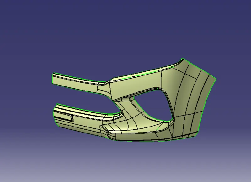
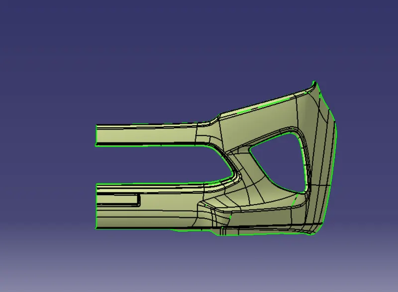
Creation of C SURFACE:
Class-C surfaces connect class-A and class-b surfaces. Interior surfaces that are difficult to see or that will be covered by another item when assembled are frequently described as Class C surfaces.
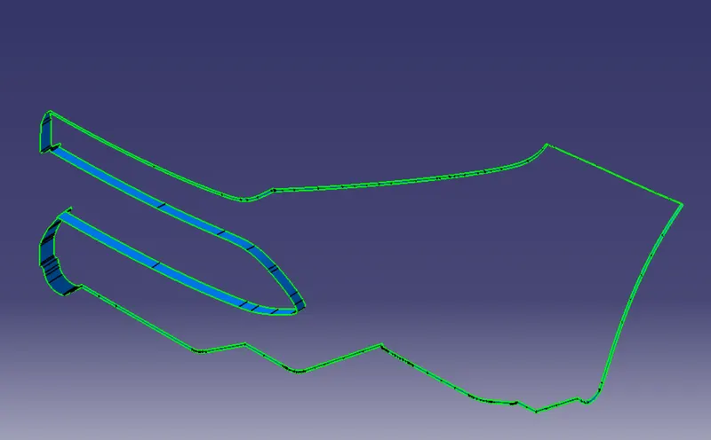
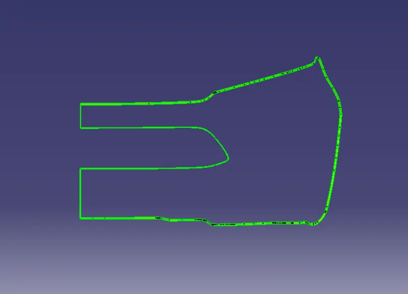
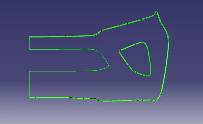
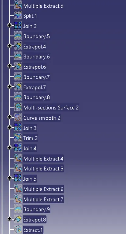
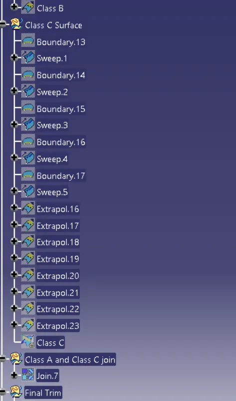
We cannot just generate the class-A border curve and sweep it all at once since it is a complicated class-A surface. As a result, we must first use the multi-extract command to construct smaller curves, and then use the surface option to make a sweep of 90 degrees. To pass the Draft analysis, sweeps at the middle of the bumper must have a 93 degree vaue. Calculate extrapolation and remove sweep surface corners at necessary edges. Using the join command, combine the sweeps to form a class-C surface.
Creating the final Bumper surface:
The CLASS-A surface and CLASS-C surface are joined first.
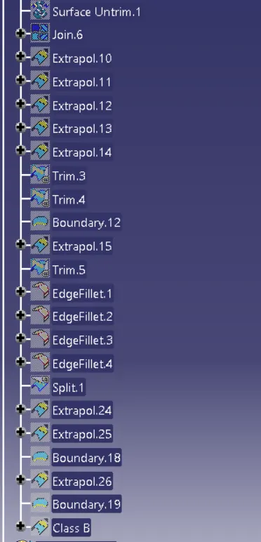
To create the final bumper surface, trim the joined surface with CLASS-B surface.
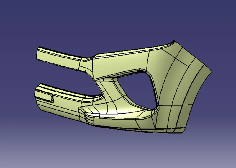
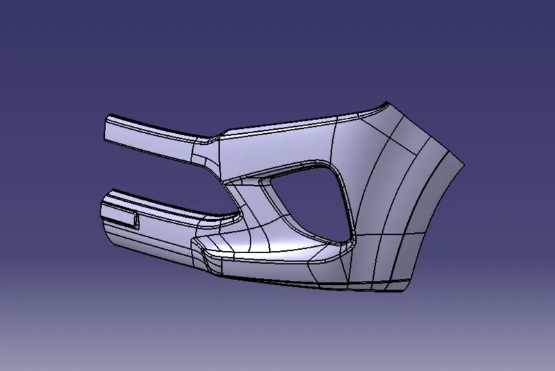
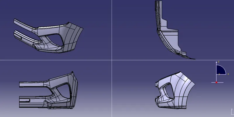
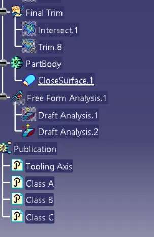
Create the base bracket solid part body and 3D Part model in multiple orientations (isometric, front, side, and top view) on the part design workbench by using the close surface command.
Draft analysisof the last section body:
The Draft analysis of the CLASS-A surface is conducted using the same process.
- Use material shading as the view mode selection.
- Align the tooling axis with the compass.
- Perform the Draft analysis while locking the Draft direction.
The Part Body's Part and the Geometric Set's Expanded Tree Structure:
Conclusion:
Using the provided Class-A surface and the tooling axis in the CATIA surface workbench have created the Bumper's Class-B and Class-C surfaces.