Week 9 - Challenge 3 - Bumper
AIM:Create the Bumper Plastic component through the given Class-A Surface.
INTRODUCTION:
Create the Bumper Plastic component through the given Class-A surface. To begin with, the tooling axis for the given Class-A Surface should be created meeting the requirements of the draft angle and at the end perform the Draft analysis on the model.
Take the Thickness of the component to be 3 mm.
OBJECTIVE:
- To create a tooling direction.
- To perform draft analysis for given Class A-Surface .
- To design the B-Surface and C-Surface using the given Class-A surface.
- Take the Thickness of the component to be 3 mm.
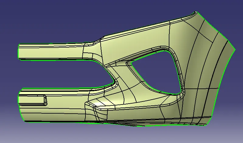
- CLASS A SURFACE
Class-A surface means aesthetic surface
TOOLING AXIS:
Tooling direction is main consideration for plastic part and mold parts because it defines movement of mold part and possibility of plastic part to come-out from mold part.
Tooling axis represents the opening and closing of the mold core and cavity.
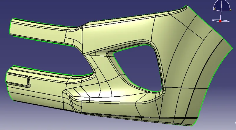
- Check the best tooling direction for the given surface.
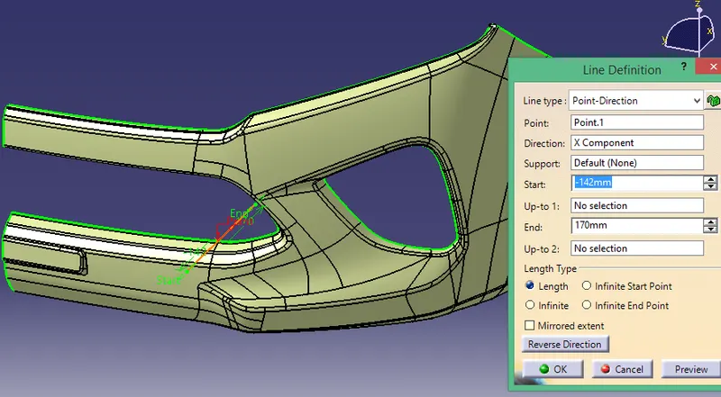
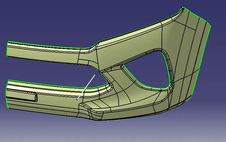
- Best tooling direction for the pumper class-A surface is along x-axis direction.
- Create a point on curve.
- Draw the line through that point in x-axis.
DRAFT ANALYSIS:
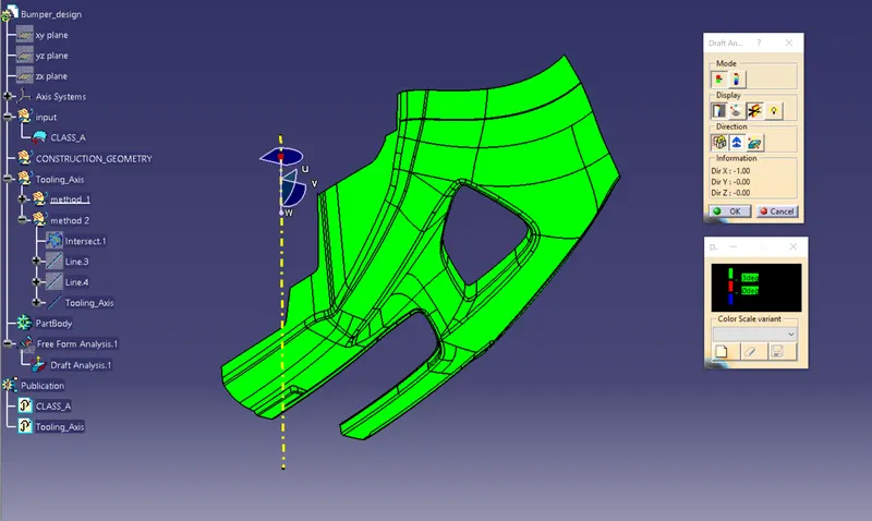
Draft analysis for the given CLASS-A surface,
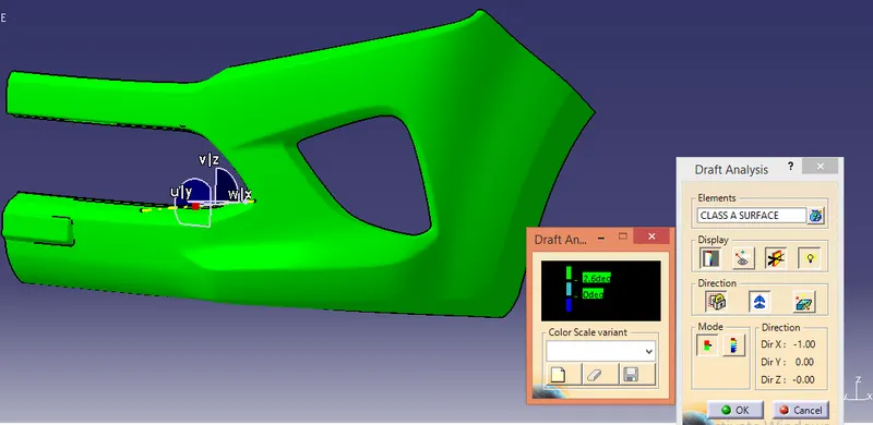
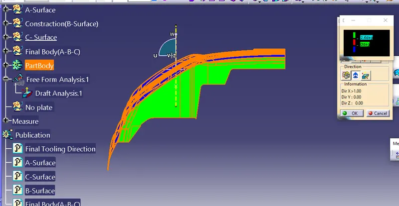
Draft analysis is done after determining the tooling axis, draft analysis is used to check whether the minimum draft (3 degrees) is maintained or not.
- Open the featured draft analysis tool.
- Drag and align the compass on the Tooling axis.
- Lock the draft direction and perform draft analysis by clicking on the component.
- CLASS B SURFACE
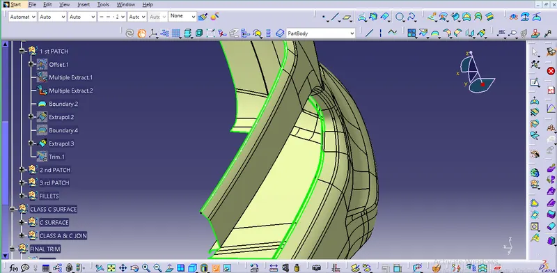
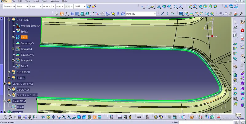
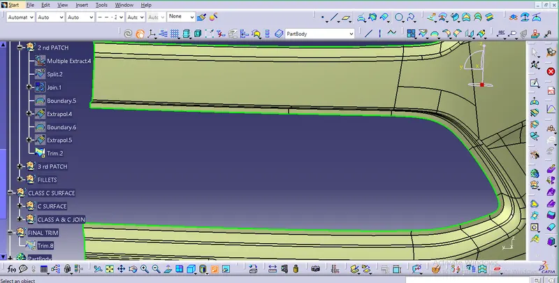
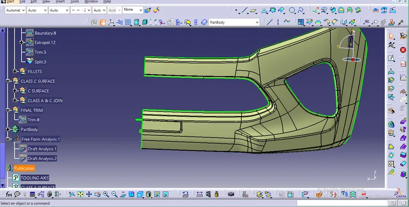
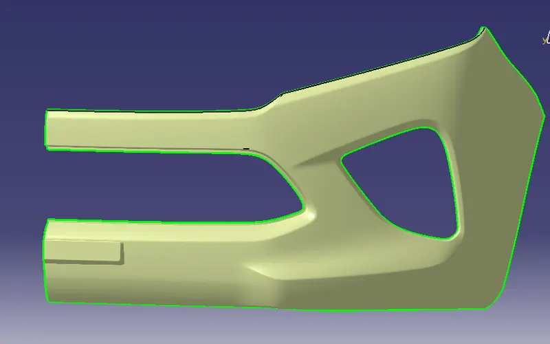
Class B Surface is created With the help Class A Surface
- Offset the class-A surface to 3mm inward direction.
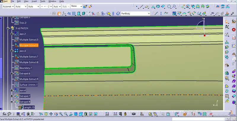
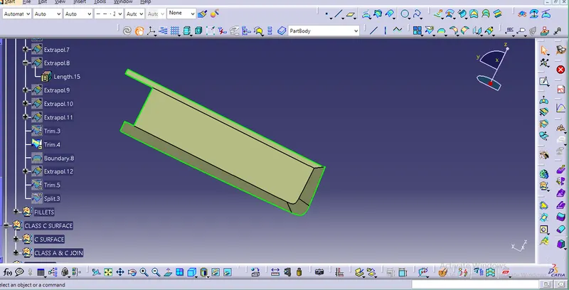
- Remove patches and discontinuity of the offset surfaces using the features like extract, multi-extract, sweep, extrapolate.
- To ensure there is no gap in Class-B surfaces ,check the boundary command to find out the boundary.
CLASS B
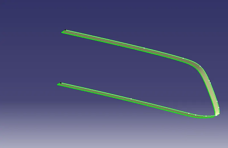
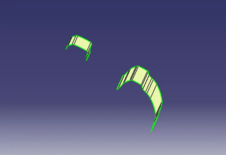
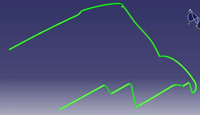
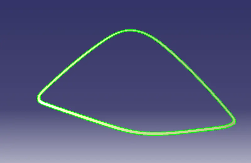
- CLASS C SURFACE
Class C is created with help of A-Surface,The Surface that joins class-A and class-B surfaces.
- Create Boundary
- Sweep it.
- Extrapulate.
- Trim off the sweep surfaces.
CLASS C
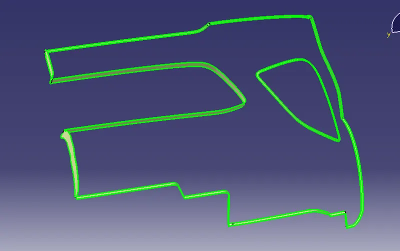
JOIN CLASS C & CLASS A
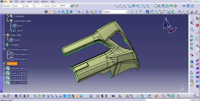
- FINAL SURFACE OF BUMBER
Trim the Joined surface with CLASS-B surface to achieve the final Bumper surface.
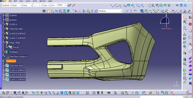
In part design work bench and using the close surface command create the base bracket solid part body.
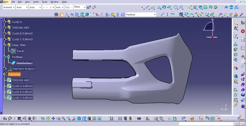
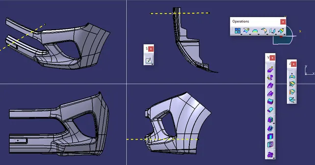
3D Part model in various orientations (Isometric, Front, Side, and Top View)
DRAFT ANALYSIS:
On final Body,
- Change the view mode to Material Mode.
- Align the Compass with Tooling axis.
- Lock the draft direction and perform the Draft analysis.
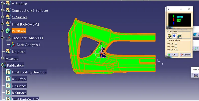
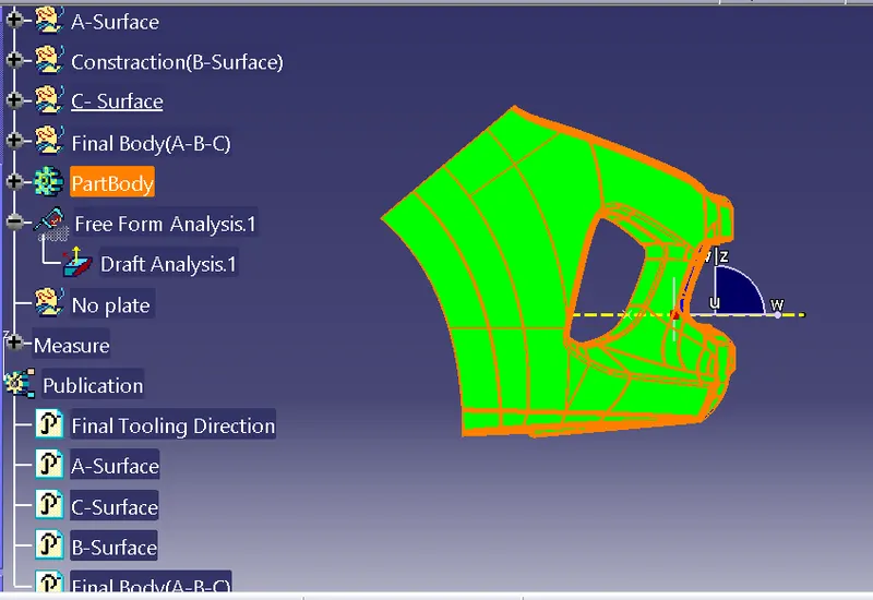
RESULT:Thus the challenge is successfully created the class-B and Class-C surfaces of Bumper using the given Class-A surface along with the tooling axis in the CATIA surface work bench.