Week 9 - Challenge 3 - Bumper
REPORT ON BUMPER DESIGN
AIM
The aim of this Bumper Design is to create a bumper model from the given class- A Surface. Also create the proper tooling direction and do draft analysis on both the class- A surface and final component.
INTRODUCTION
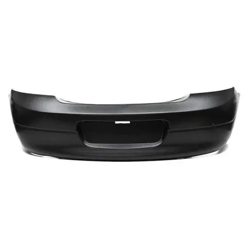
A bumper is a bar attached transversely in front of or behind a car body to prevent contact between an obstruction and the car body or to cushion the shock of collision between vehicles. Without the protection of a bumper, a minor collision could cause significant and costly damage to your car. Bumpers offer protection to other vehicle components by dissipating the kinetic generated by an impact. Most OEM bumpers are made out of plastic and feature an aluminum or steel reinforcement bar hidden in the middle. Some bumpers may also contain polypropylene in order to help absorb energy during an impact.
METHODOLOGY
For desining the bumper we go for the further procedure like -
- Tooling Direction Creation
- Do Draft Analysis on Class-A Surface
- Creation of Class-B Surface
- Creation of Class-C Surface
- Do Final Trim to get Closed Surface
- Create Final Component
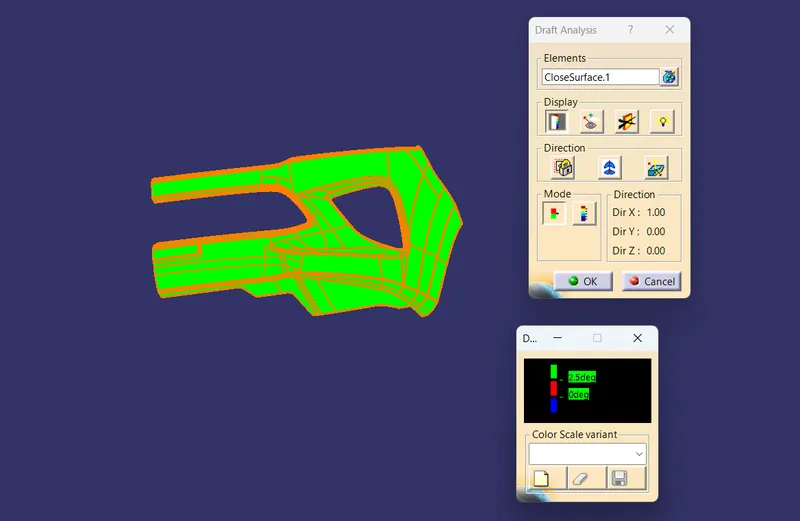
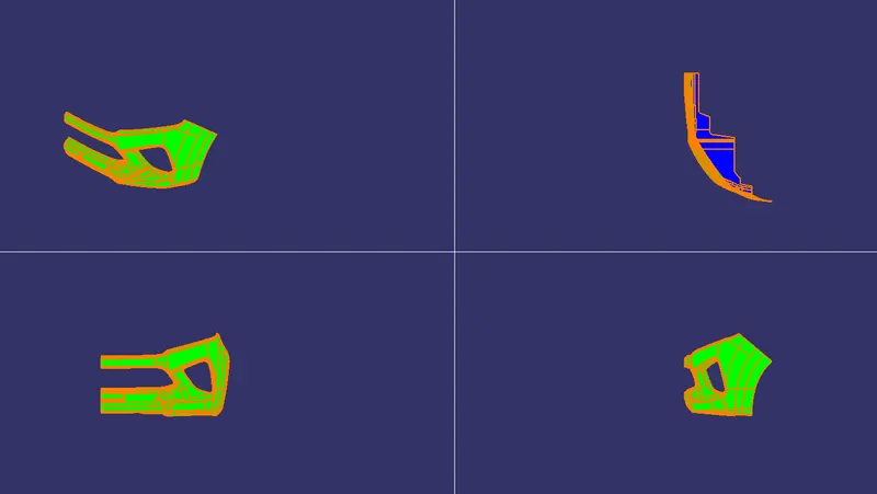
- Do Draft Analysis on Final Component
Tooling Direction Creation
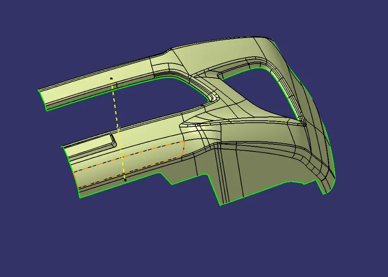
Tooling axis represents the opening and closing of the mold core and cavity during the manufacturing of the components. A plastic product designer should consider the best tooling direction to cutdown the cost of the component very less.
For creating the tooling direction first we Check the best tooling direction for the given surface. Then with the help of line, we create the proper tooling axis.
Draft Analysis on Class-A Surface
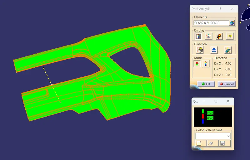
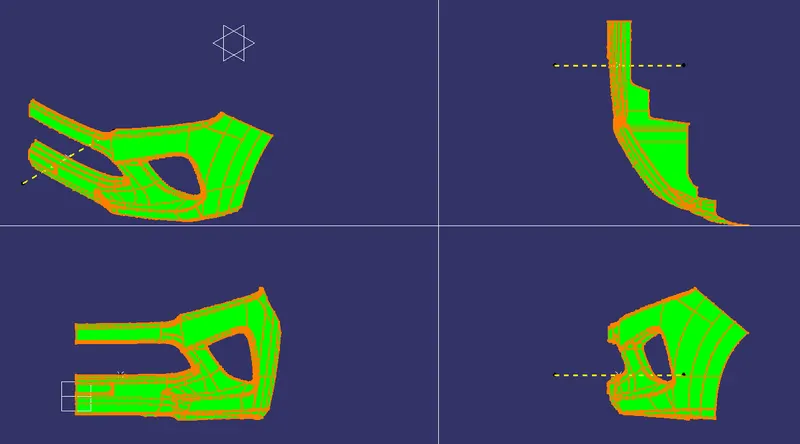
The Draft Analysis is a command enables you to detect if the part you drafted will be easily removed. This type of analysis is performed based on colour ranges identifying zones on the analysed element where the deviation from the draft direction at any point, corresponds to specified values.
Draft analysis is done after determining the tooling axis, draft analysis is used to check whether the minimum draft (3 degrees) is maintained or not.
Creation of Class-B Surface
Class-B surface means thickness of a part it is not visible and is inside part. In other words, Class-B surface is a surface below a certain thickness from the class-A surface. This is the surface that contains engineering aspects of a model.
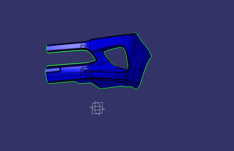
Creation of Class-C Surface
Class C surface joins class-A and class-B surfaces.
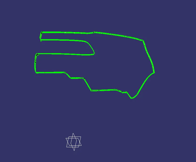
Do Final Trim to get Closed Surface
After creating the class B and Class C surface, we join the Class A and Class C surface then we do final trim to get the complete closed suface.
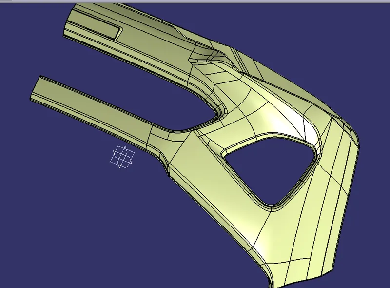
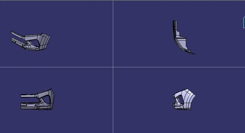
Create Final Component
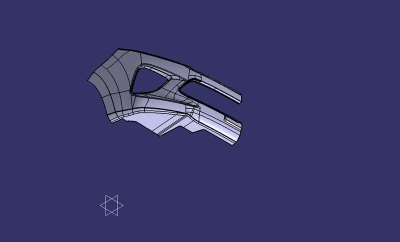
Different Orientation of Final Component -
Do Draft Analysis on Final Component
Draft Analysis on Final Component in Different Orientation -
CONCLUSION
We have discussed about Bumper and the procedure for designing the bumper. We also did the draft analysis on both the class A suface and the final component.