Week 9 - Challenge 1 - Base Bracket Design
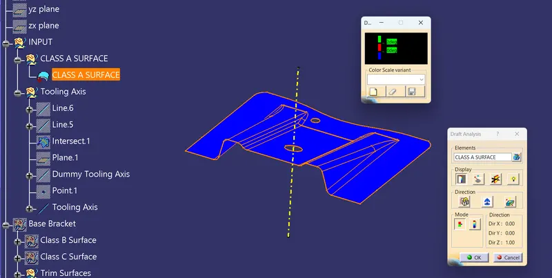
Screenshot of Draft Analysis Report for Class-A Surface and The Final Plastic Component :-
Class-A Surface -
Final Component -
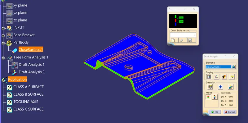
Screenshot of Solid Model With Colour Code of Draft Angle in Different Orientations -
Isometric View -
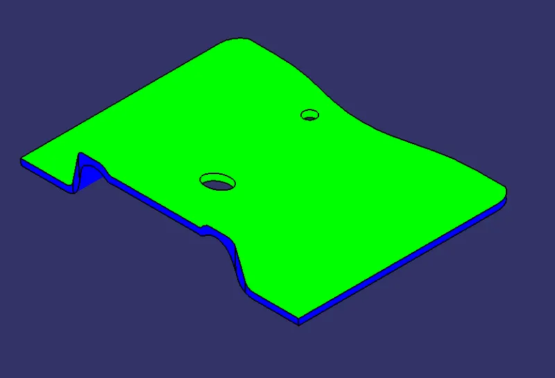
Front View -
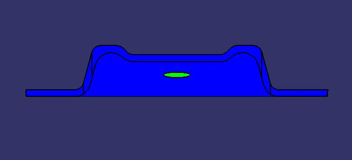
Top View -
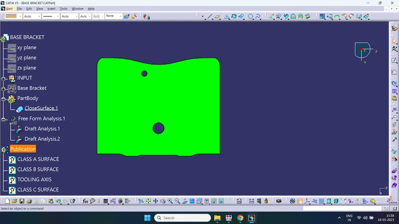
Side View -
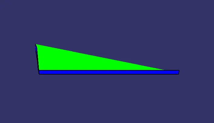
REPORT ON DRAFT ANALYSIS AND TOOLING AXIS CREATION -
So, as you can see in the below pictures for the steps i have used to create the tooling axis -
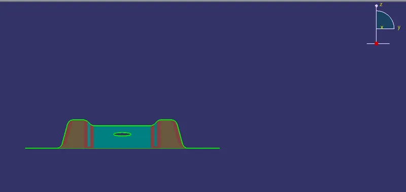
in above image we can see that when we look at the X-Axis Direction, there is another hole on the class A surface which is not clear in this axis. so are not going with this axis.
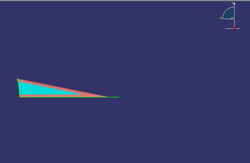
In Y-Axis Direction, We can see that there is no any hole get clear in this direction. So we can not go with this axis also.
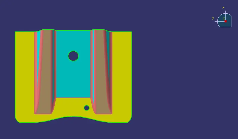
So when we look at the Z-Axis Direction of Class-A Surface, we can see that all the holes and surfaces get clear through this axis. therefore, we are taking Z-Axis Direction for Creating Tooling Axis.
let's go to step for creating Tooling Axis -
First we create a Dummy Tooling Axis -
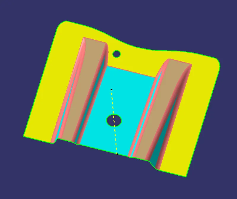
Then we Create an Intersection of Class-A Surface -
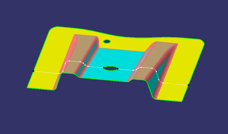
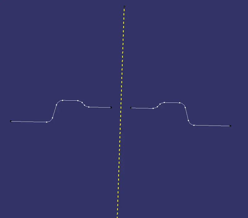
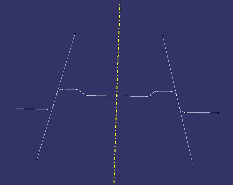
After that, we create two lines -
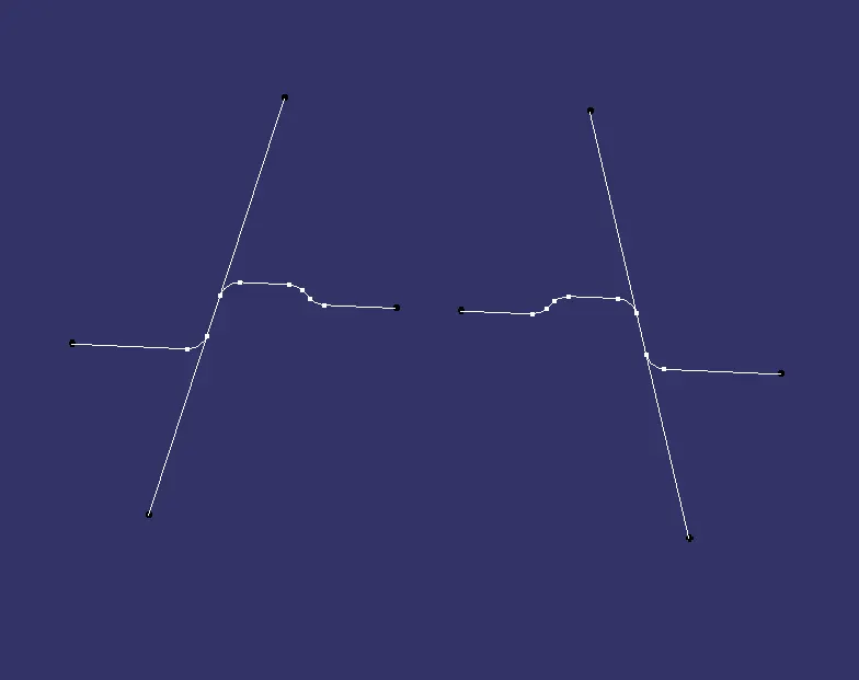
Then go to the point of these two intersection lines and create the Tooling Axis.