Week 9 - Challenge 3 - Bumper
AIM
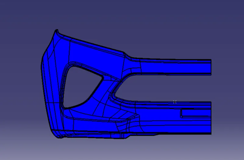
Create the Bumper Plastic component through the given Class-A surface. To begin with, the tooling axis for the given Class-A Surface should be created meeting the requirements of the draft angle and at the end perform the Draft analysis on the model.
Take the Thickness of the component to be 3 mm
DESIGNING OF BUMPER COMPONENT
TOOLING AXIS FOR GIVEN CLASS A SURFACE
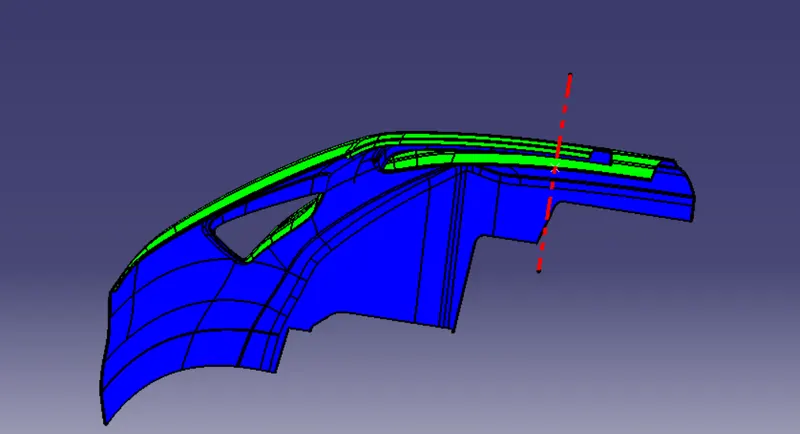
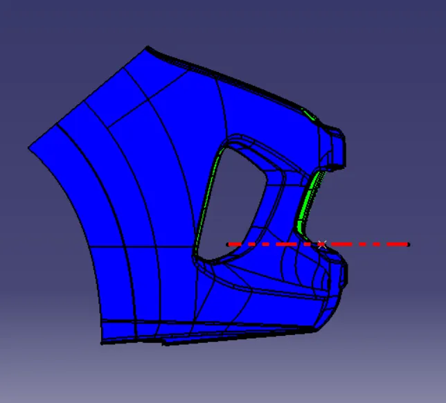
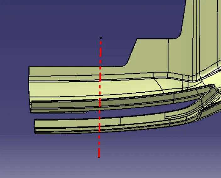
First create a tooling axis for the given class A surface .In this direction the mold opens and closes .
Examine the given class a surface and it clear that the given class a surface has projected profiles and holes in X direction.Thus X axis is consider as the main tooling direction.
DRAFT ANALYSIS OF CLASS A SURFACE
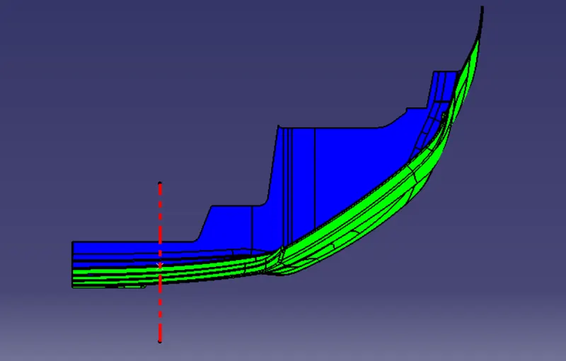
Check the draft analysis of the given class A surface using the main tooling axis to ensure the part has minimum draft angle (3 degree) in all faces .
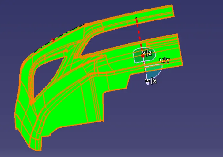
CLASS B SURFACE
Class B surface created from the class A surface .offset the class A surface required thickness and work on the offsetted surface to create the class B surface.
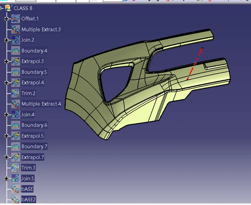
CLASS C SURFACE
Class C surface connecting the class A and B surfaces.Extracting the boundary of class A surface and using the swept with reference surface to create the class C surface.The angle should be 90 degree with reference surface .Appropriate length provide to create the class C surface.
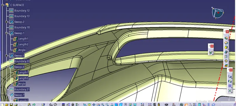
Then join the class A surface with class C surface
Finally trim with class B to get the closed surface of bumper .
DRAFT ANALYSIS OF FINAL SOLID BODY
Use the draft analysis to check the final solid product has minimum draft angle.
here all the surface has minimum draft angle 3 degree .