Week 9 - Challenge 3 - Bumper
CHALLENGE TITLE _ BUMPER DESIGN
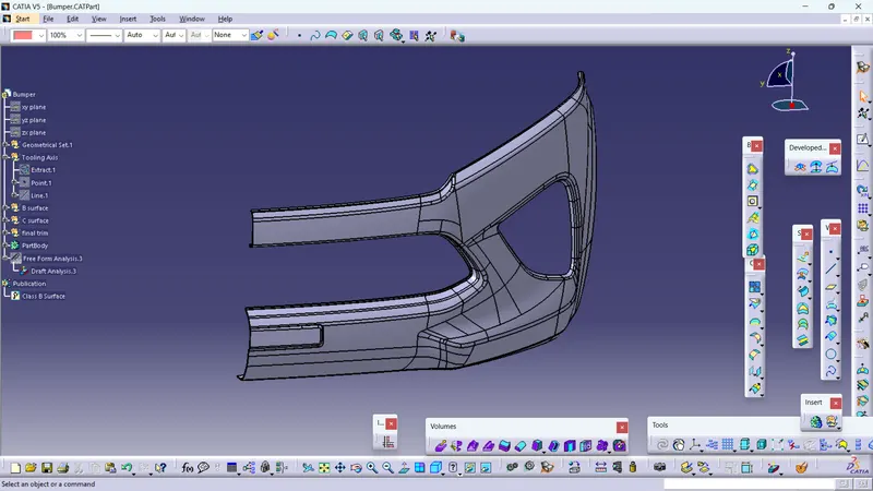
Objective : Creating the Bumper Plastic component through the given Class-A surface.
Introduction :
The Class-A surface refers to the outermost surface of a plastic model that is created by the designer for aesthetic purposes and serves as input for the plastic modeler.
Class-B surface, on the other hand, is located beneath a particular thickness from the Class-A surface and contains the engineering aspects of the model.
Finally, Class-C surface refers to the surface that joins the Class-A and Class-B surfaces together.
Procedure followed :
1. Methodology - Creating tooling axis > Then performing draft analysis for conforming the inputs given >Then creatingClass-B surface > And finally creating Class-C surface
2. Tools Used - Extract
Un-trim
Trim
Extrapolate
Offset
Edge fillet
Boundary
Sweep
Join
3. Steps Followed -
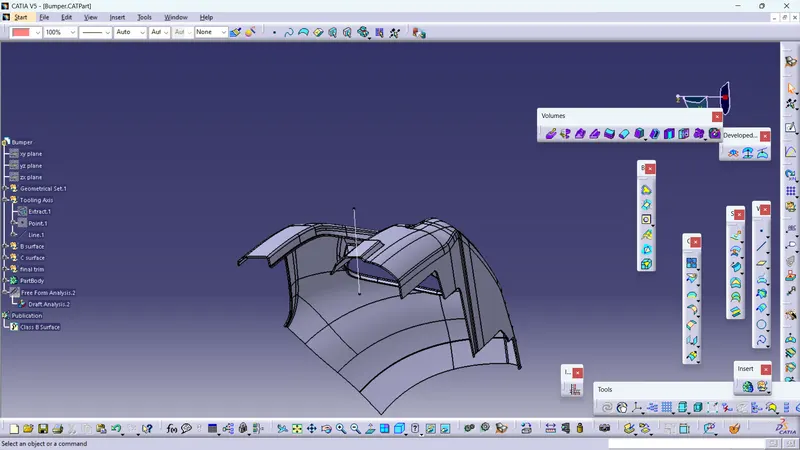
A. Creating tooling axis - The tooling axis is a critical factor in determining the orientation of a component in mold, core, and cavity design, as it indicates the direction in which the mold opens. To establish the tooling axis, the inertia method is employed, and the following steps are followed:
First, the A-surface is selected, and the "Measure Inertia" option is chosen.
Next, the "Create Geometry" option is selected in the Measure Inertia window, followed by selecting "Non-associative geometry."
Then, the "Center of Gravity" option is clicked, creating the Inertia point.
The component is viewed in all three axes, X, Y, and Z, to determine the appropriate direction for the Tooling axis.
Based on the assessment, the X-axis is chosen as the Tooling axis, and a line is created using the CG point and the X-direction as the direction of the line.
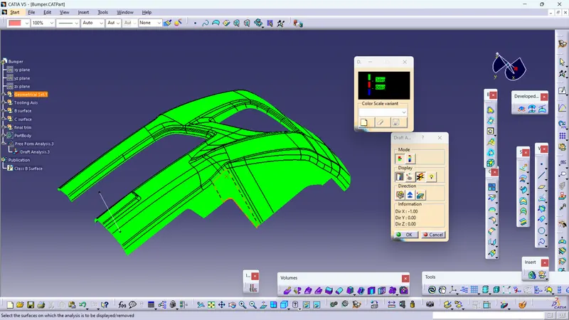
B. Draft Analysis - Draft Analysis is a tool that allows users to analyze a 3D part model to ensure it has the proper draft angle. A draft angle refers to the amount of taper for molded or cast parts perpendicular to the parting line. To perform a draft analysis, the user selects the part or surface and the pull direction, which can be changed as needed.
In CATIA, the Draft Analysis provides color-based identification, making it easy to identify surfaces that are clear or stuck. By setting the draft angle to 3 degrees, the software displays green for surfaces that have a draft angle greater than 3 degrees, blue for surfaces with a draft angle of 0 to 3 degrees, and red for surfaces with a draft angle less than 0 degrees. If a red zone is identified, it means the draft angle is insufficient, and the user must create a tooling axis using another method or request a design change from the engineer.
C. Creating Class B surface - This Surface is the surface located behind the Class A Surface, and it is usually not visible. This surface is created by adding a certain distance or thickness, such as 2mm or 3mm, to the Class A surface.
We've taken a thickness value as 3mm, As given in the problem statement.
D. Creating Class C surface -
The A and B surfaces are interconnected through an additional surface known as the C surface. This is accomplished by employing a sweep operation, utilizing the A surface as the reference while creating a curve derived from the boundary of the same surface.
Furthermore, the creation of A surfaces involves utilizing a sweep with draft direction technique.
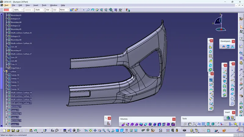
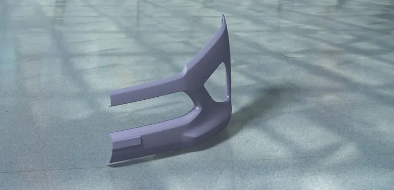
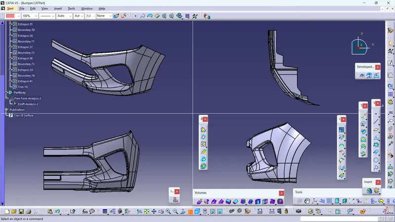
FINAL MODEL DRAWINGS IN DIFFERENT VIEWS
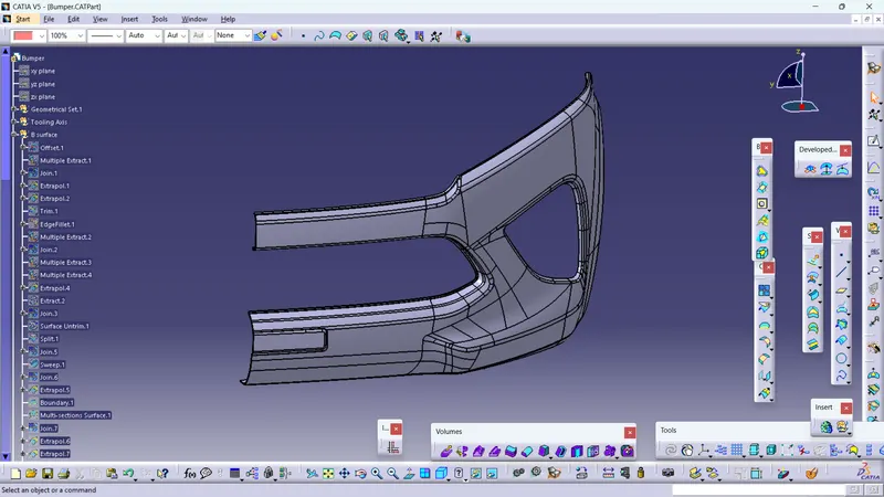
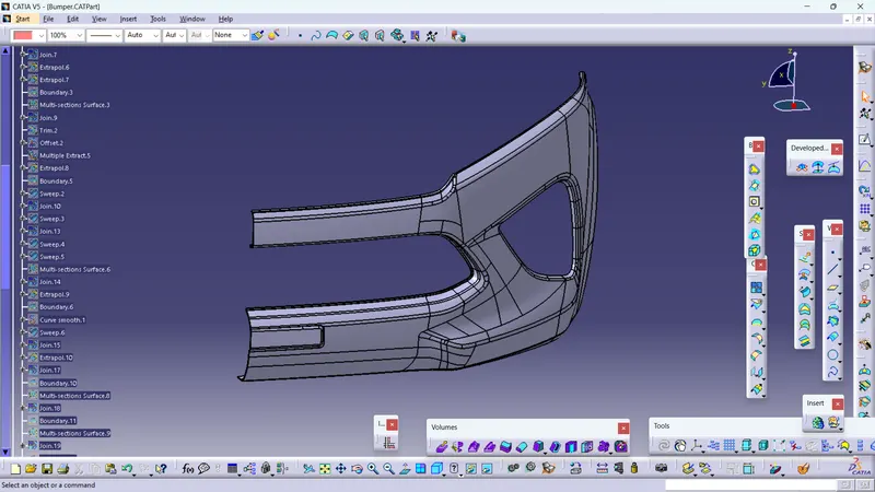
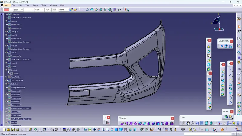
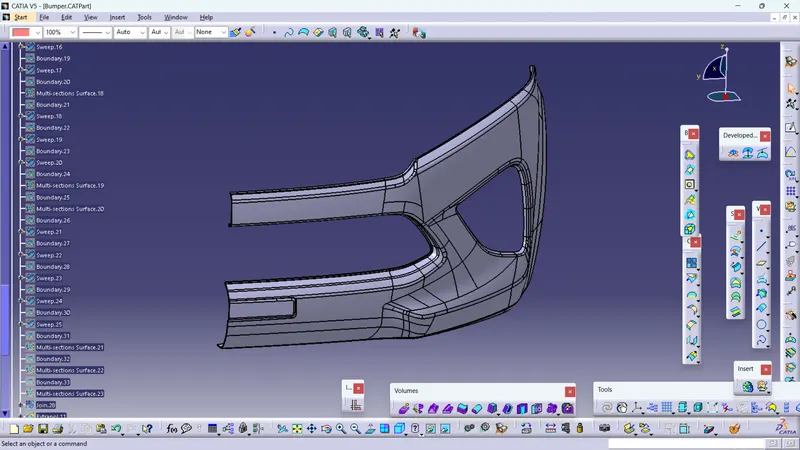
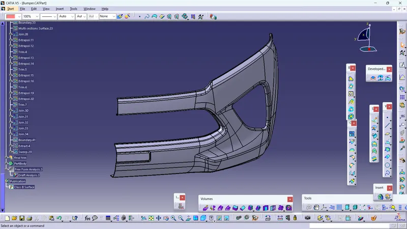
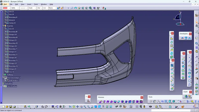
TREE STRUCTURE