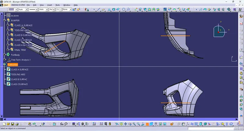
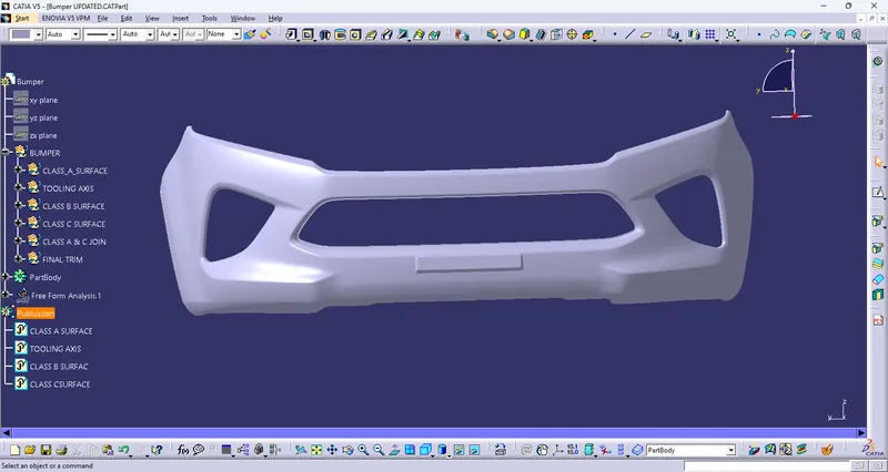
Week 9 - Challenge 3 - Bumper
Week 9 - Challenge 3 - Bumper
Objective- Create the Bumper Plastic component through the given Class-A surface. To begin with, the tooling axis for the given Class-A Surface should be created meeting the requirements of the draft angle and at the end perform the Draft analysis on the model.
Take the Thickness of the component to be 3 mm
CLASS A SURFACE:-
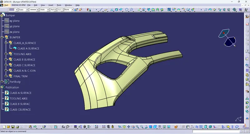
In automotive design application Class A Surfaces are created on all visible exterior surfaces (ex; body panels, bumper, grill, lights etc.) and all visible surfaces of see-touch & feel parts in interior (ex: Dashboard, seats, door pads etc.). This can also include beauty covers in the engine compartment, mud flaps, trunk panels and carpeting.
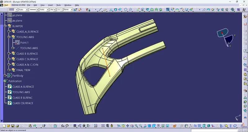
TOOLING AXIS-
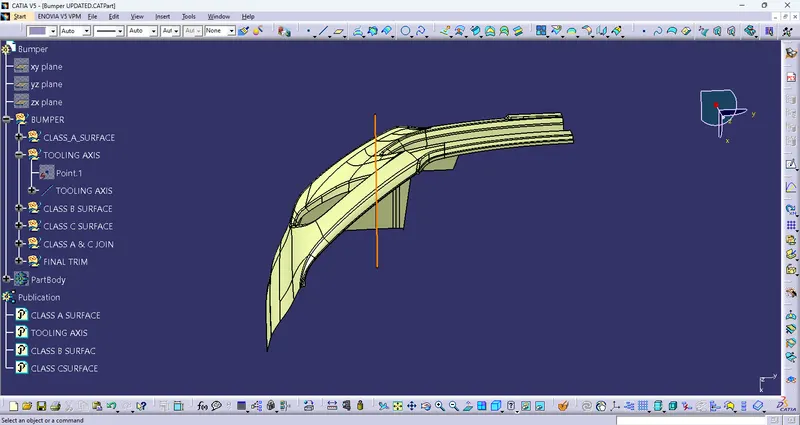
Now find the tooling axis of the component. The tooling axis is nothing but the mould opens or cavity opens. Check visaully which is the best possible tooling axis.
DRAFT ANALYSIS OF CLASS A-
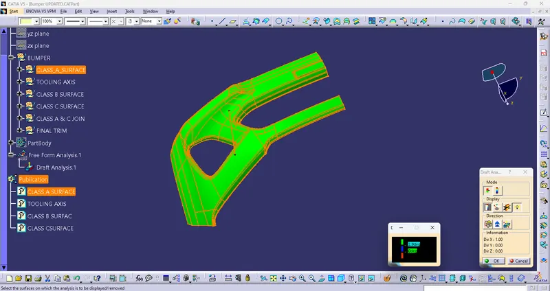
Draft analysis-
The Draft Analysis command enables you to detect if the part you drafted will be easily removed. This type of analysis is performed based on color ranges identifying zones on the analyzed element where the deviation from the draft direction at any point, corresponds to specified values.
CLASS B SURFACE-
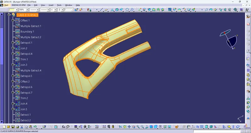
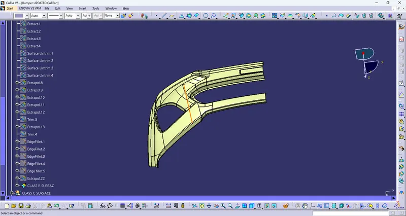
The surface which is back side of Class A surface is called Class B Surface. Mostly it not visible. It is created with the help of Class A surface with some distance (thickness) like 3mm etc.
CLASS C SURFACE-
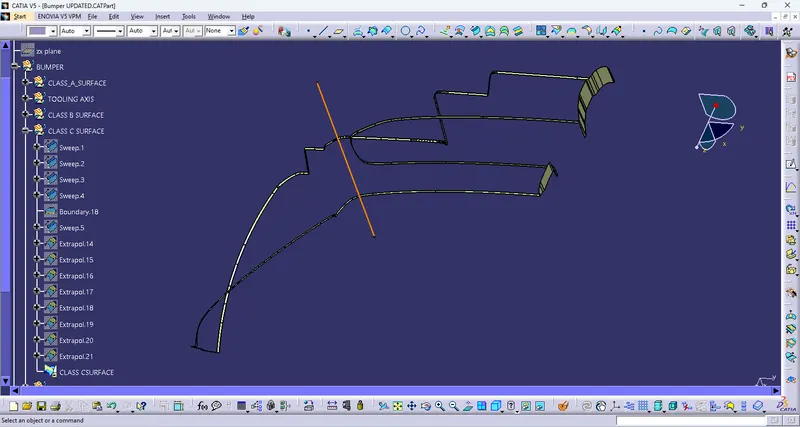
FINAL JOINING-
CLASS A WITH CLASS C-
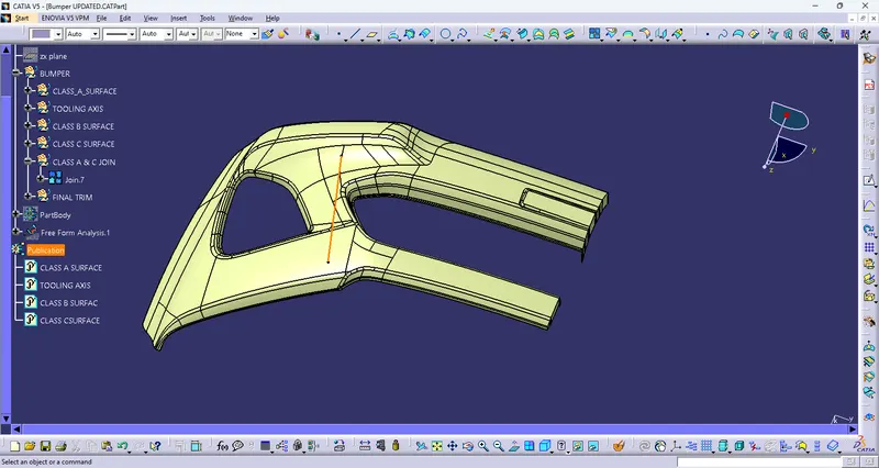
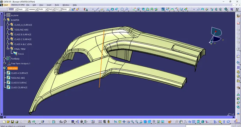
CLASS A AND CLASS C WITH CLASS B-
CLOSE SURFACE-
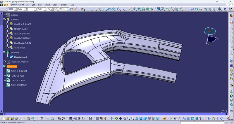
DRAFT ANALYSIS ON FINAL PRODUCT-
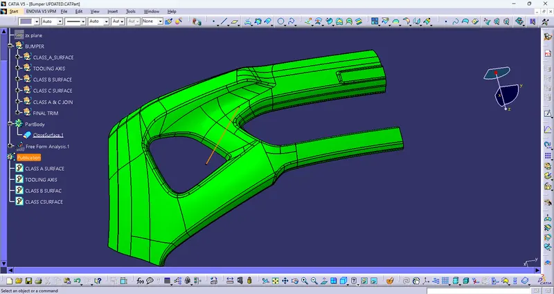
FINAL PRODUCT-