Week 9 - Challenge 3 - Bumper
AIM: To create the Bumper Plastic component through the given Class-A surface and perform draft analysis on the final plastic component.
Objective:
- Create the Tooling Axis
- Creation of class B and Class C surface
- Creating a solid part out of surface modeling
- Draft analysis of class-A surface and final bumper component.
Thickness of the component = 3 mm
Tool used: CATIA V5
Introduction: In this project we are designing a Bumper using given class A surface. The approach includes creation of Class B surface keeping 3 mm thickness in mind for the complete component. The design also included Class C creation from the given parent surface.
Constraints:
- No change in Class A are allowed.
- Part thickness can't deviate by more than +- 30%
- All design rules should be strictly followed.
- All surfaces should be closed before converting to solid
- All faces should meet the allowed draft requirements.
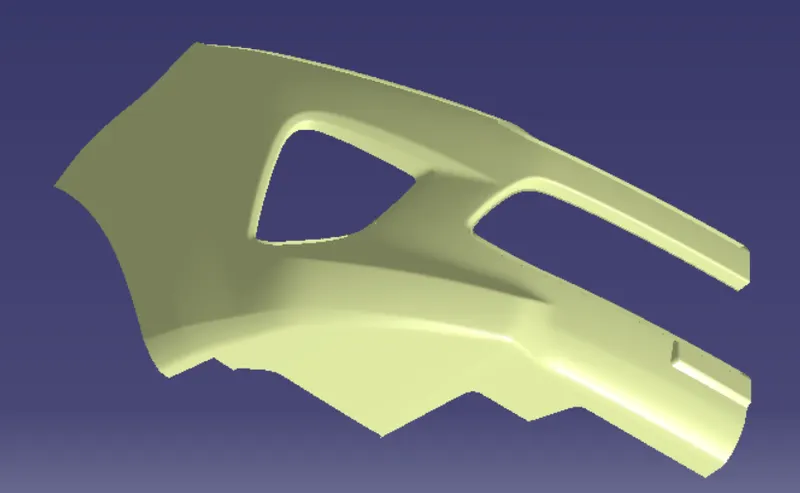
CLASS A: Following surface is given as the input for the component creation.
TOOLING AXIS:
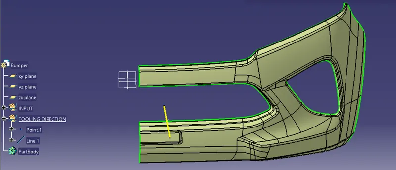
First we have to observe and study the class A surface to create the "Tooling Axis" for the component, and for the above given bumper x-axis is the best suitable tooling axis. Initially, I create a dummy tooling axis on x-axis by considering the reference point created on the any curve of the bumper. This dummy tooling axis, we can use as main tooling direction axis but here first we have to check class A surface making an angle direction inbetween 0-3 degree by draft analysis method.
DRAFT ANALYSIS:
To perform draft analysis, click on Insert>Analysis>Feature Draft Analysis
Once the draft analysis toolbar is opened, go to the display block and select the 'Analysis under the running point' command to check the angle for different sides (walls and inclined plane angles) on the class A surface. The color scale on the bottom visualizes, whether the draft angle meets the requirements or not (3 deg) by indicating the colors Green, Blue and Red. Once the draft angle analysis was done, we need to align and fix the compass to the tooling axis of the class A surface.
To align and fix the compass to the tooling axis, go to the Direction block in the draft analysis toolbar and click on the 'Use the compass to define the new current draft direction option (or just click on the compass symbol). Now bring the compass to the surface and align it to the tooling axis of the class A surface and click on the lock symbol beside the compass in the direction block. Once we click on 'ok' on the draft analysis toolbar, we can finish the draft analysis process.
NOTE: First check shading is in material mode (Go to the customise view parameter)
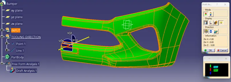
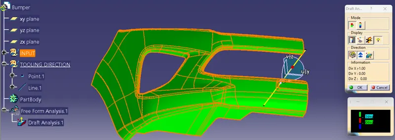
We can clearly see in the above figure draft angle is set to be 3 degree and all the surfaces are in green color it means dummy tooling axis is now main tooling axis.
CLASS B SURFACE:
To create te class-B surfeace, I will go through the direct offset method becouse here the give bumper surface are very difficult to find out where to start class-B surface so to do that we have to directly offset it upto desired thickness and then we will go through, like some part are missing in offset surface. So that surface we have to fill by using extraction, untrimmed, extrapolation, trimming, joinning tool in surface design workbench etc.
Here it showing warning that some element or patches are missing so we have to click "OK".
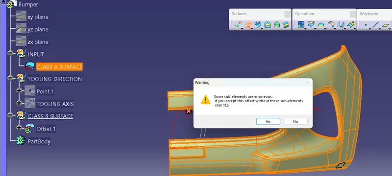
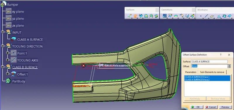
Now we have to fill all the patches which is missing so to do that we are going one by one.
UPPER PATCHES
First working on this patch
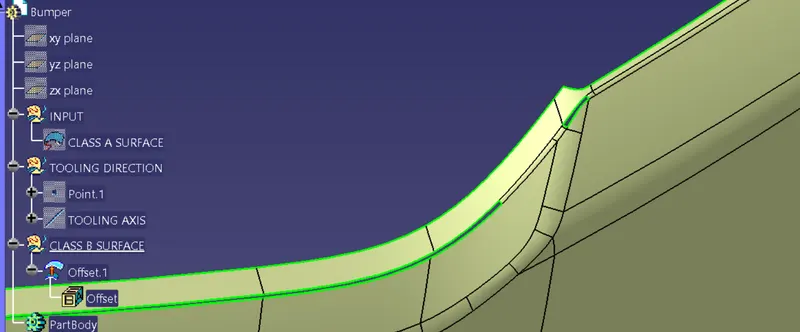
Extract the pacthes where the fillets is missing
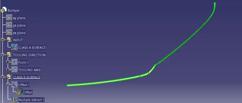
Extract other side of surface fillet missing
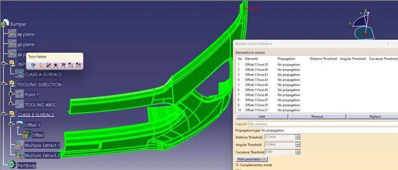
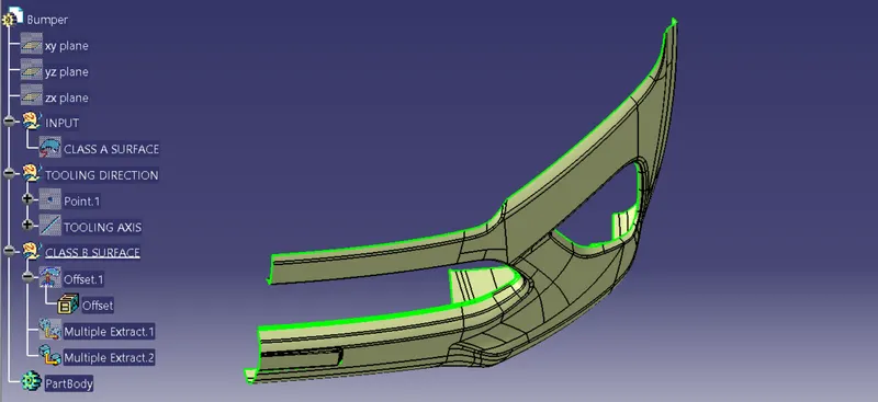
Now create boundry and extrapolate it till the surface are going to intersect eachother
Here we do extrapolation on that surface but it shows error while extrapolating so for do that we have to extract some extract patches from that surface and then extrapolate and trim them.
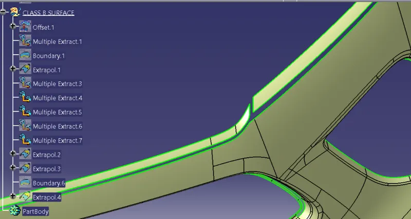
Extrapolate it upto required surface intersection
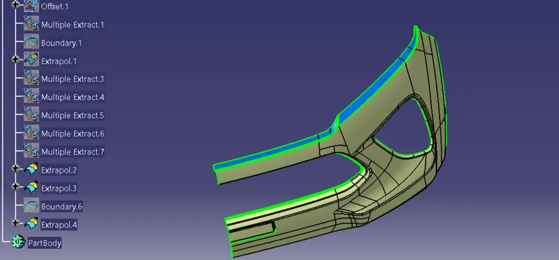
Trim that surface
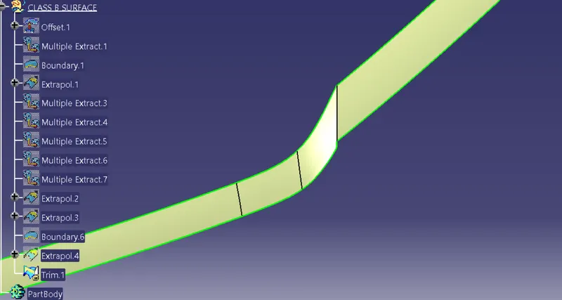
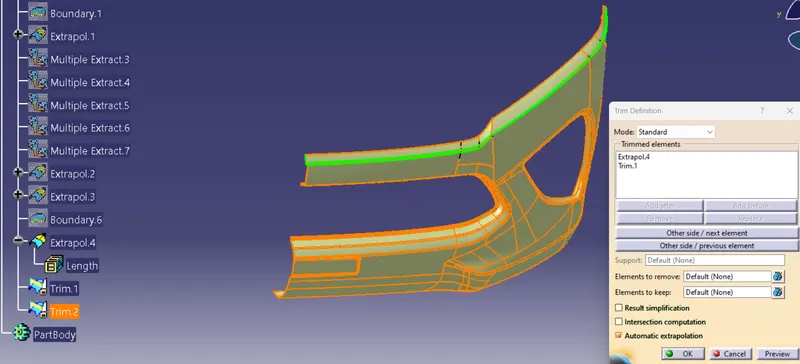
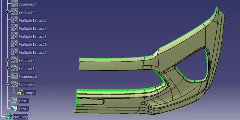
Now unhide the first extrapolation and trim them out
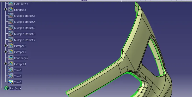
Give fillets at the edges of the surface trim
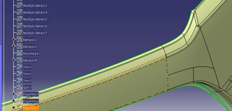
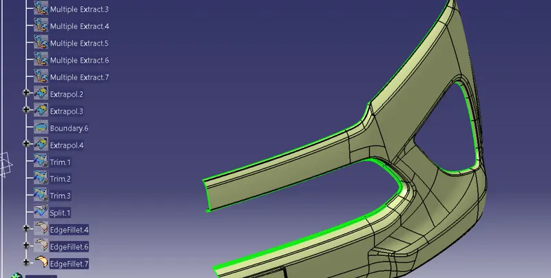
MIDDLE PATCHES
Here we can see some patche are missing so now we have to fill them and make a appropriate surface
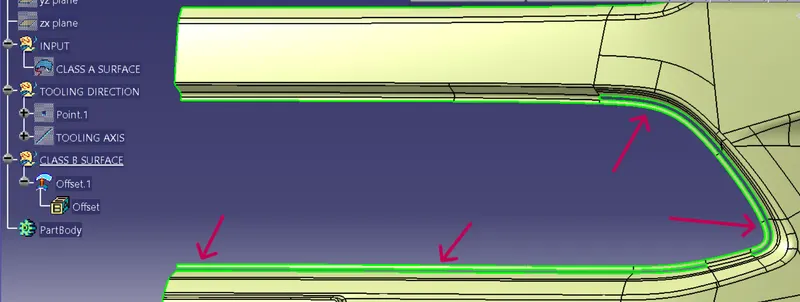
Here we have to extract missing patches and thier adjecent surface
Extract missing part and then use split command to split the surfaces
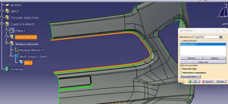
Use join command to remove subelement
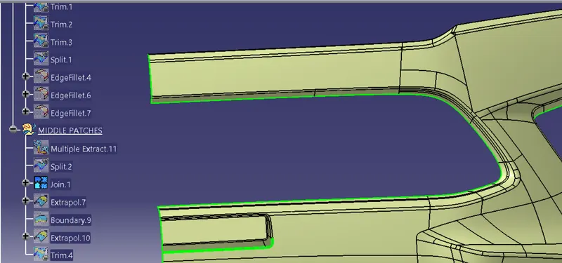
Create boundry and then extrapolate and then trim
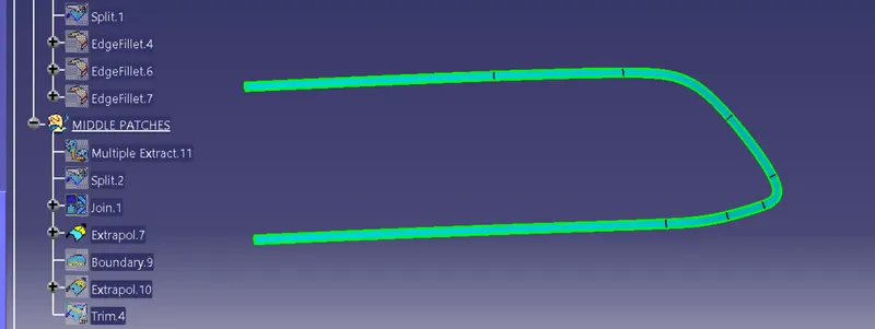
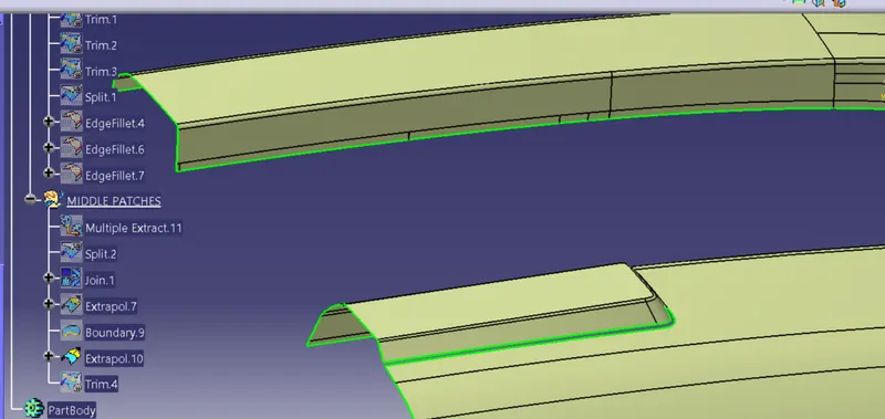
TRIM IT
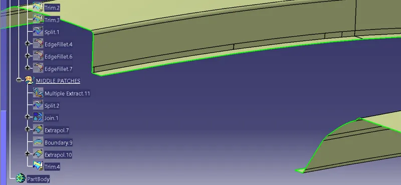
LOWER PATCHES
We have to remove some patches from the middle patches by using join method
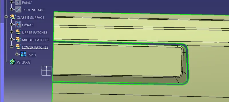
Extract both the side patches
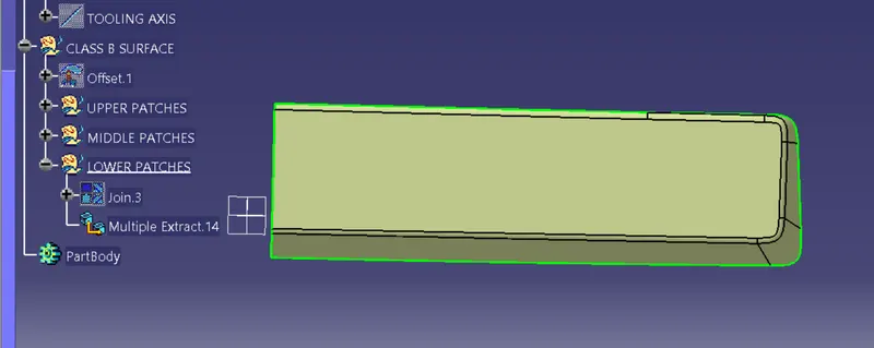
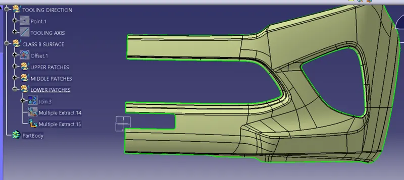
Now by using join method remove some subelement
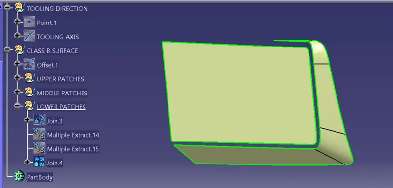
Now etract both the surface and extrapolate it
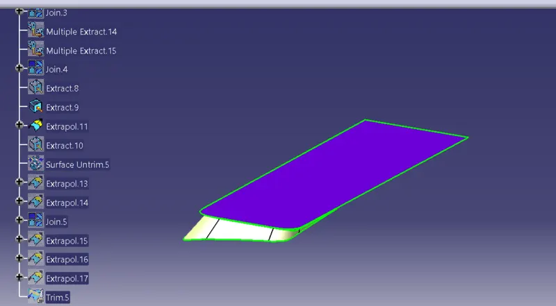
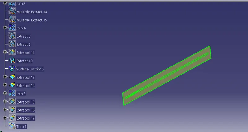
Now we have to extrapolate second surface also by the use of join command to remove some surface and extrapolate it
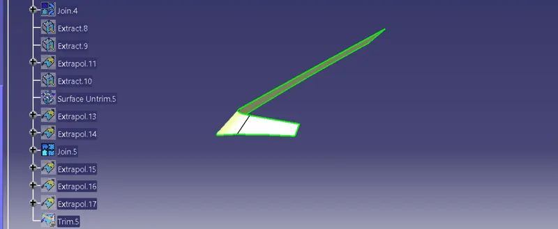
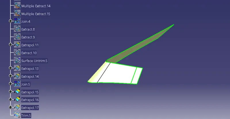
Now unhide both the surface and trim it
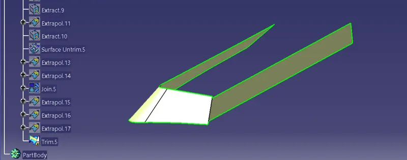
Unhide the top surface and trim it
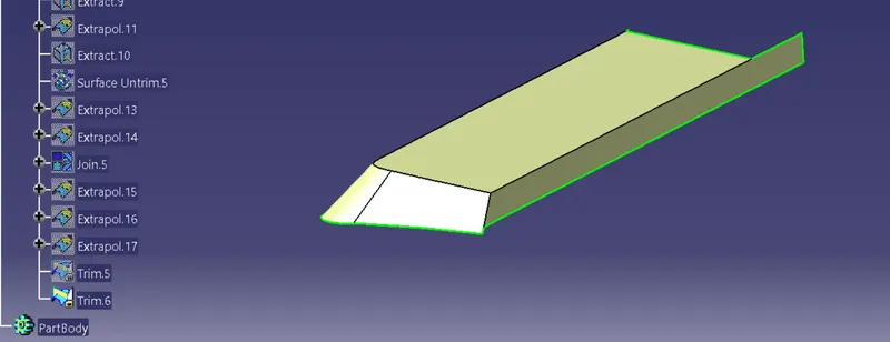
Extrapolate the base surface upto intersection
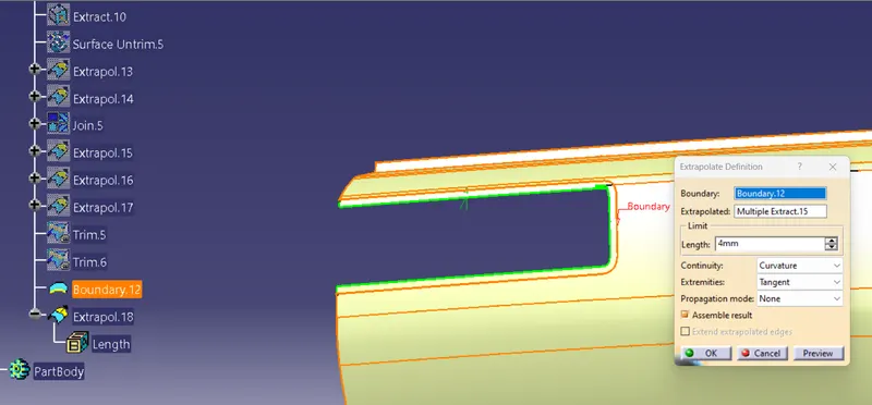
Trim both the surfaces
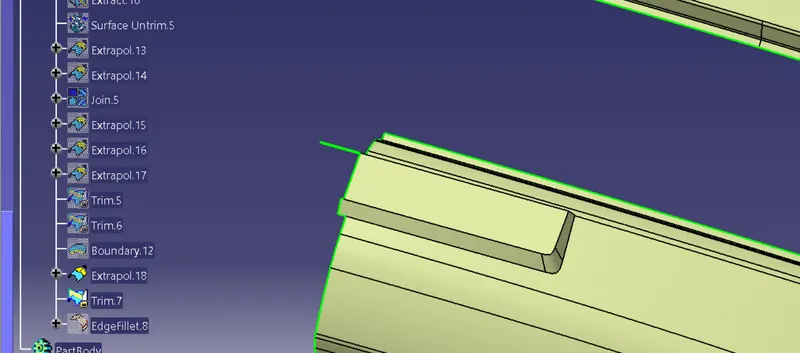
Give fillets to the edges
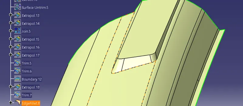
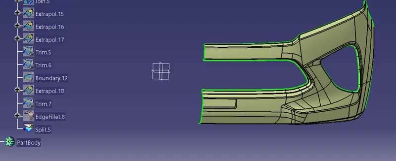
CLASS C SURFACE
It is the combination of Class A, Class B and Class C surfaces. To create a class C surface, I used the sweep command by considering the outer boundary of the class A surface. In the sweep command, go to the 'line' command in the 'profile' block and the subtype is 'with draft direction'. Now select the outer boundary and tooling axis, give 3 deg in the angle (the draft angle for a plastic component is 0.5 to 3 deg) and select the direction to sweep, in this condition the class B surface is under the class A surface so select the inside down arrow to sweep. Now I joined all the sweeped surfaces by using the 'join' command and then I trimmed the Class A, Class B and Class C surfaces to make a closed surface, to make a Solid body.
Boundary creation and Sweep command:
Here we use one by one sweep and boundry command becouse there is sharp edge in the class A.
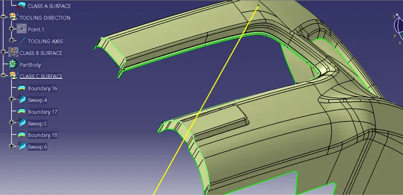
Also we have to create boundry and then apply sweep command on middle circle
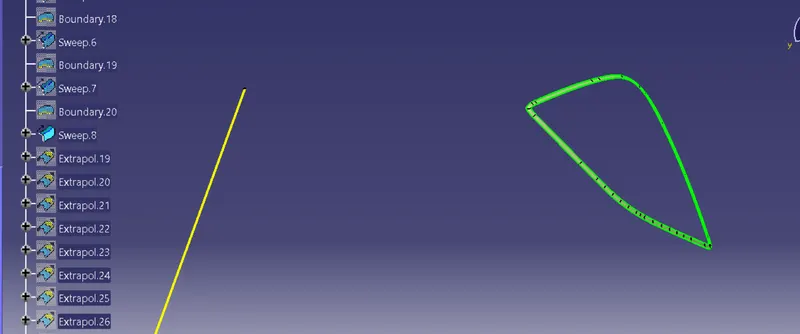
Now we have to extrapolate the edges and then trim them
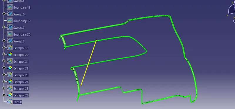
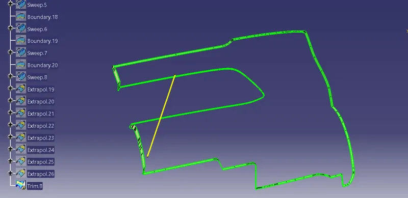
Class C surface
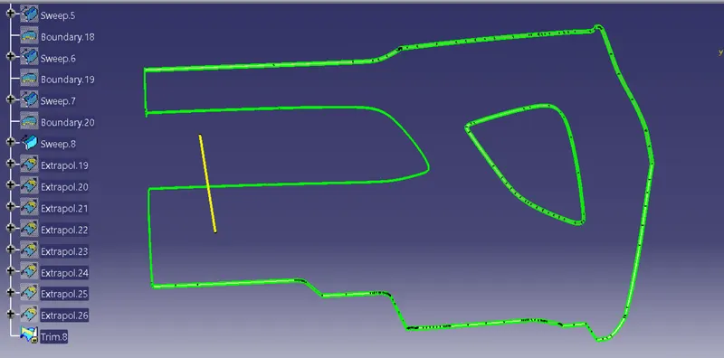
Join the class C surface with class A
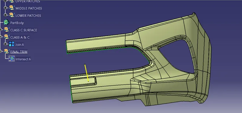
Now we have to check class B surface and joint class A & C surface by the intersection method and then trim it
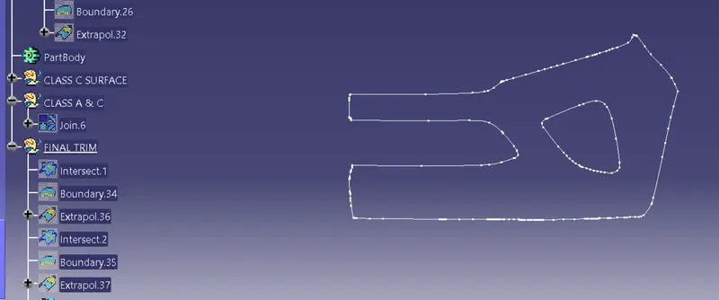
Trim class B surface with joint class A & C
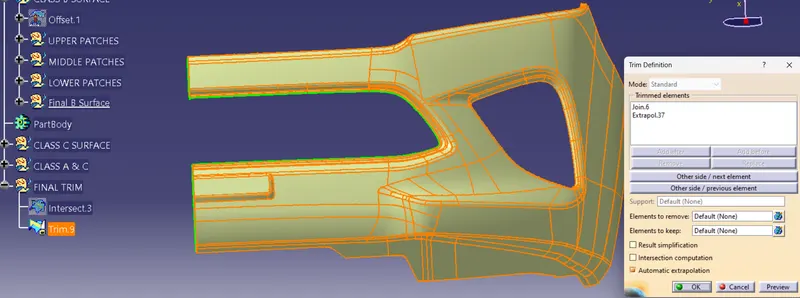
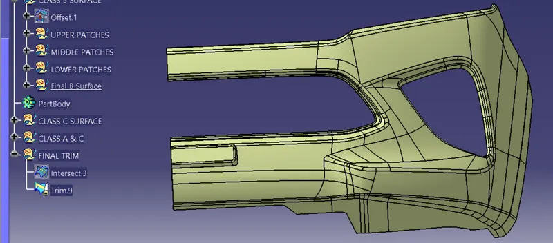
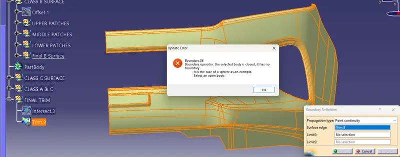
Check the final trim is fully close or not by the use of boundry command
DRAFT ANALYSIS:
Once the draft analysis toolbar is opened, go to the display block and select the 'Analysis under the running point' command to check the angle for different sides (walls and inclined plane angles) on the class A surface. The color scale on the bottom visualizes, whether the draft angle meets the requirements or not (3 deg) by indicating the colors Green, Blue and Red. Once the draft angle analysis was done, we need to align and fix the compass to the tooling axis of the class A surface.
To align and fix the compass to the tooling axis, go to the Direction block in the draft analysis toolbar and click on the 'Use the compass to define the new current draft direction option (or just click on the compass symbol). Now bring the compass to the surface and align it to the tooling axis of the class A surface and click on the lock symbol beside the compass in the direction block. Once we click on 'ok' on the draft analysis toolbar, we can finish the draft analysis process.
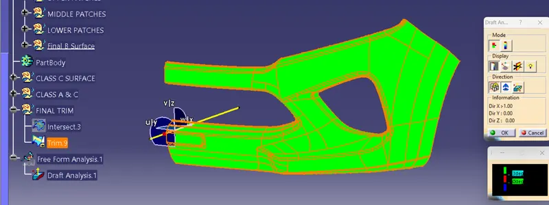
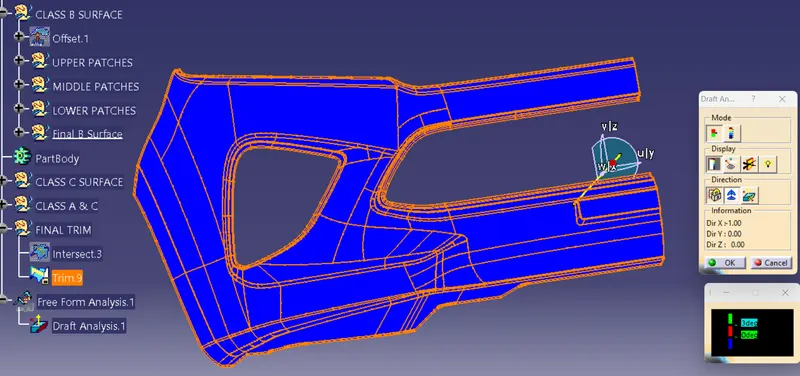
Here in the above figure we can clearly see that when the campass fixed with tooling axis all the final surface is in green color which means all the surface angle are in below 3 degree. And the close surface is in right position.
Now make this close surface into solid surface
- Switch to the part design workbench
- Use the close surface tool to make it solid
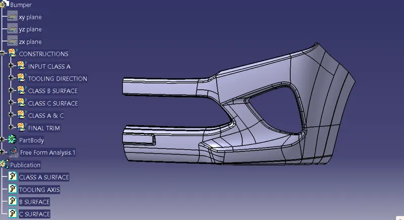
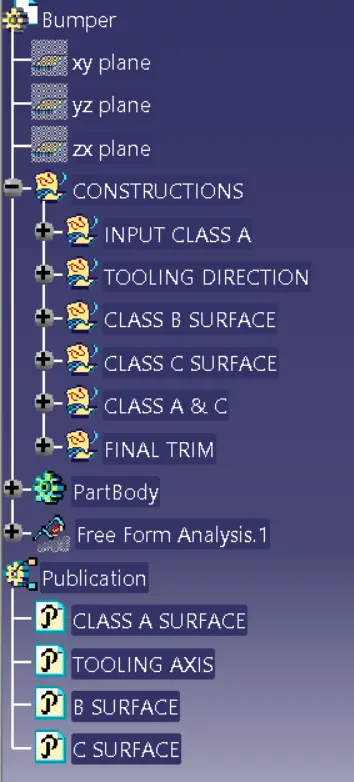
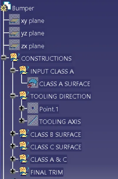
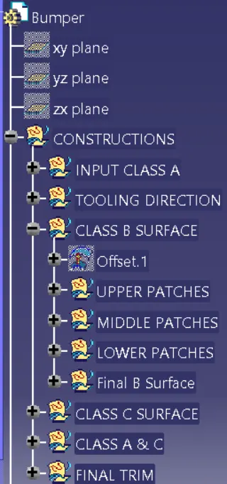
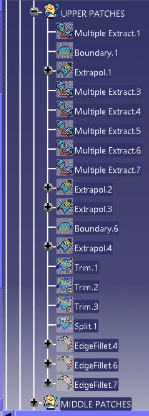
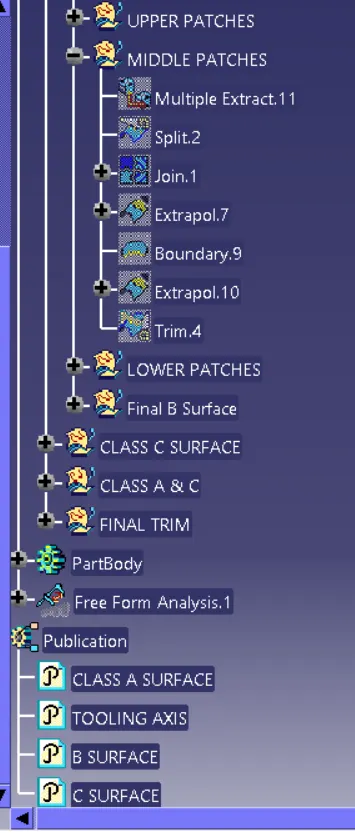
TREE STRUCTURE
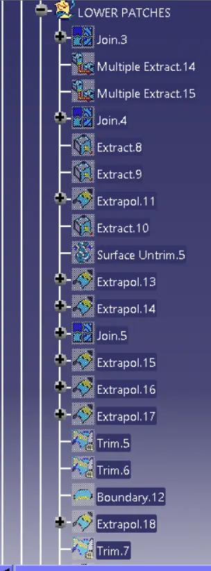
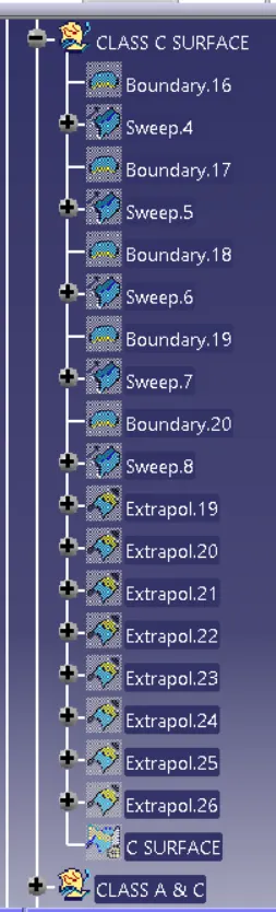
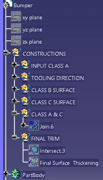
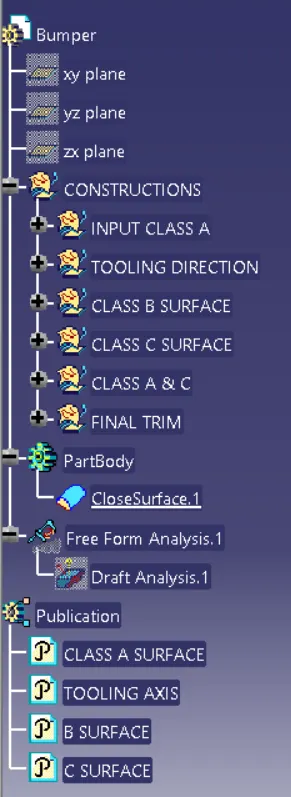
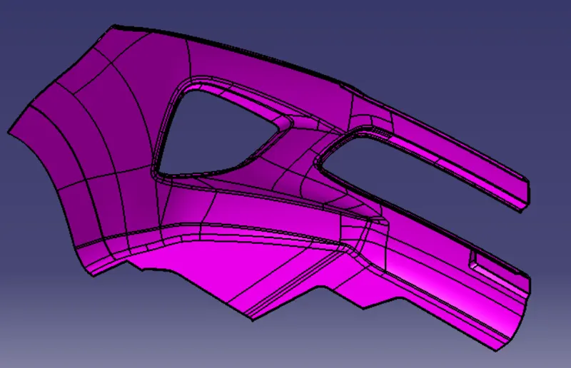
ISOMETRIC VIEW
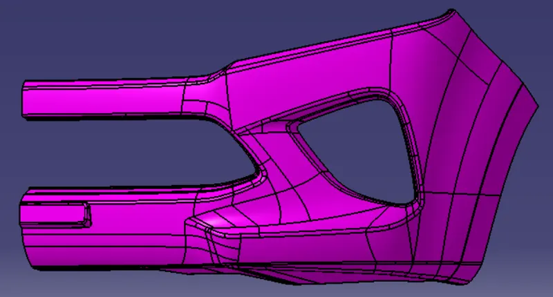
FRONT VIEW
CONCLUSION:
Here we studied bumper surface thickening where we use surface design tool to thicken the surface. We got input class A surface through this surface we create class B and Class C surface and then this surface inclosed convert into solid surface as we can see in above figure.
ISOMETRIC VIEW
LINK:
https://drive.google.com/file/d/1qefR5fCFGkVUuJ_KX9NYHmhbknHT0qtX/view?usp=share_link