Week 10 - Challenge 3 - Door Trim Lower with Engineering Features
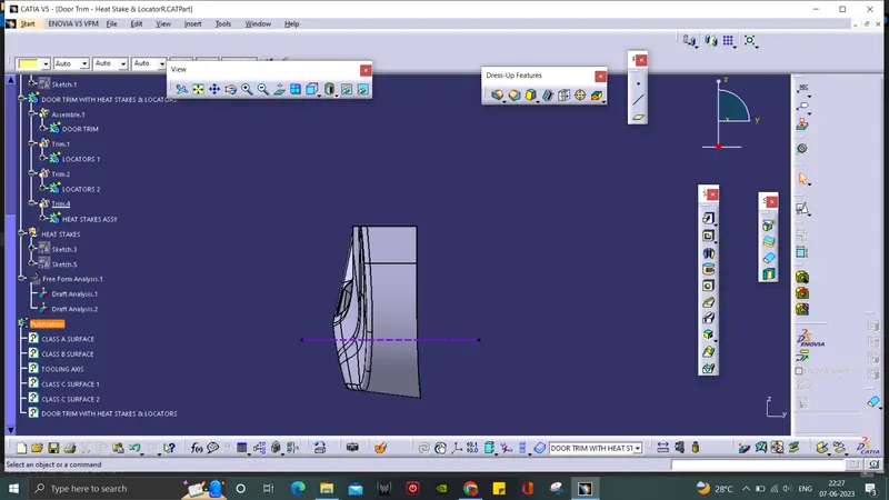
TOOLING AXIS:
- A geometrical set for Tooling Axis is created and base is extracted as referance surface.
- A point in created at the surface and y axis is taken as reference axis.
- Then a line is drawn through the point which is our Tooling Axis.
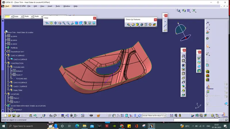
CLASS B SURFACE:
- Since we have different number of fillets, the offset method is the easy way for the B surface.
- The A surface is offsetted for 2.5mm and there will be discontinuity along the surface.
- They are repaired by using Fill, Multi-section and Join commands.
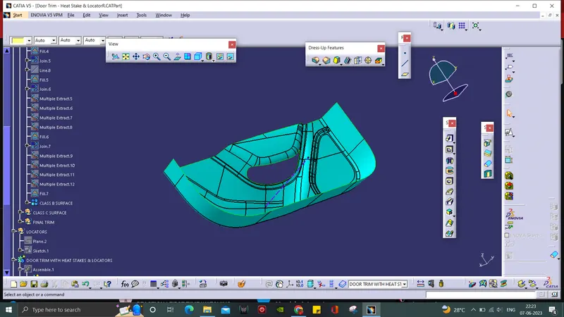
CLASS C SURFACE:
- Mutiple extract is used to form the boundary along the A surface.
- Then the boundary was made into surface by using sweep with respect to draft direction of the Tooling Axis.
- The swept surfaces were extrapolated and trimmed to form Class C surface.
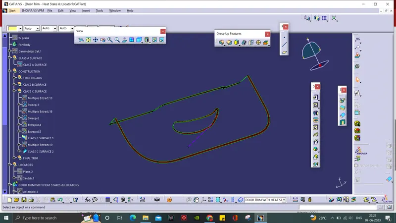
FINAL TRIM:
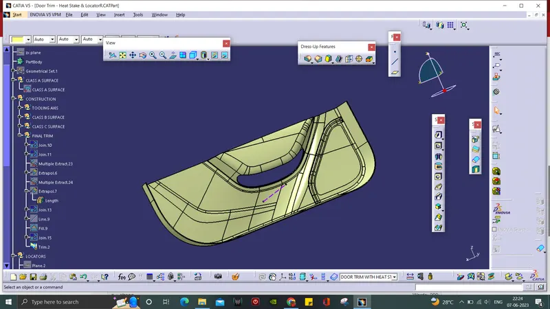
- At the final trim part, the A surface and C surface are joined together.
- The surface we get above is them trimmed with the B surface to form the Door Trim surface.
- Then at part design, the hollow part is converted into a solid Door Trim by using closed surface command.
LOCATORS:
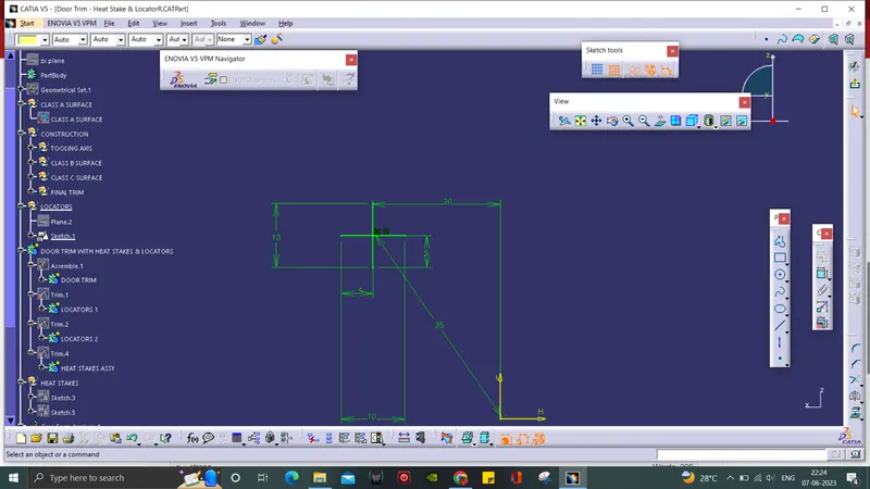
- The reference plane is taken is required area and sketch is drawn.
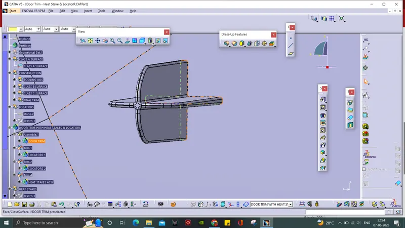
- It is padded using thick component with certain value and then drafted, chamfered and filleted.
- Another Locator is created using translation method.
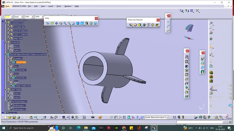
HEAT STAKES:
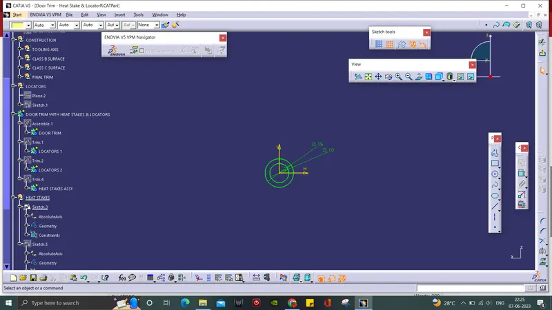
- The reference points are given, required sketch is drawn.
- Which is padded and drafted to a certain value.
- A rib for the Heat Stakes is created in sketch and padded.
- The rib is then trimmed with the Heat Stakes solid.
- Like that, 16 Heat Stakes are created by translation using reference points.
MAIN ASSY:
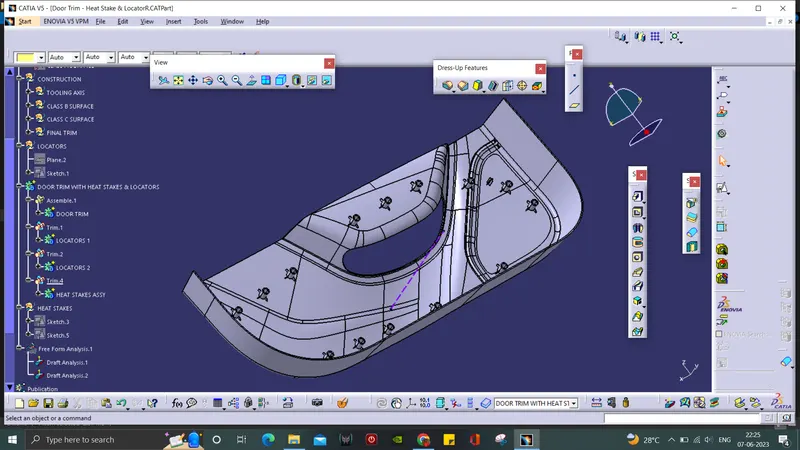
- A main body is created, so the all the sub bodies will be assembled together.
- At first, the Door Trim is assembled in the main body.
- The Locators are trimmed with the main body.
- All the Heat Stakes are assembled in a single body and then trimmed to the main body.
DRAFT ANALYSIS:
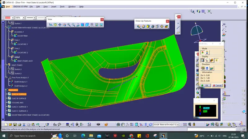
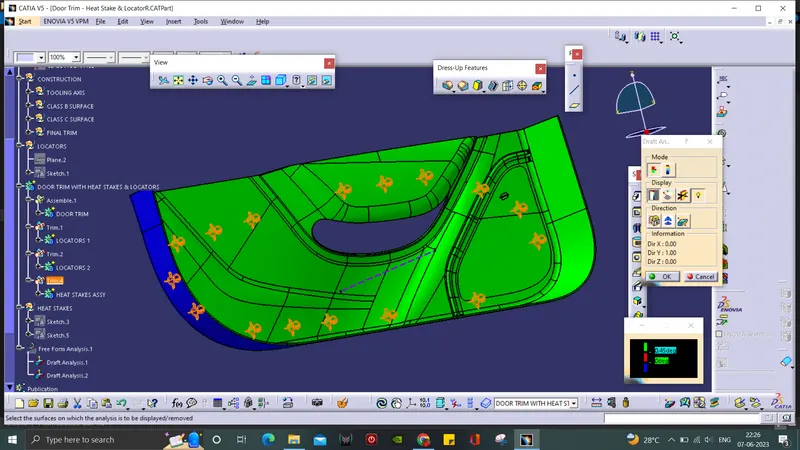
- In Draft Analysis tool bar, use the compass and drag it to set along the Tooling Axis of the surface.
- By clicking the surface, it will turn into green colour. if it is blue, the analysis was inversely done which is corrected just by flipping the direction.
- Draft Analysis on the solid part is in green and red regions.
- Individual Draft Analysis is done for both solid and surface.
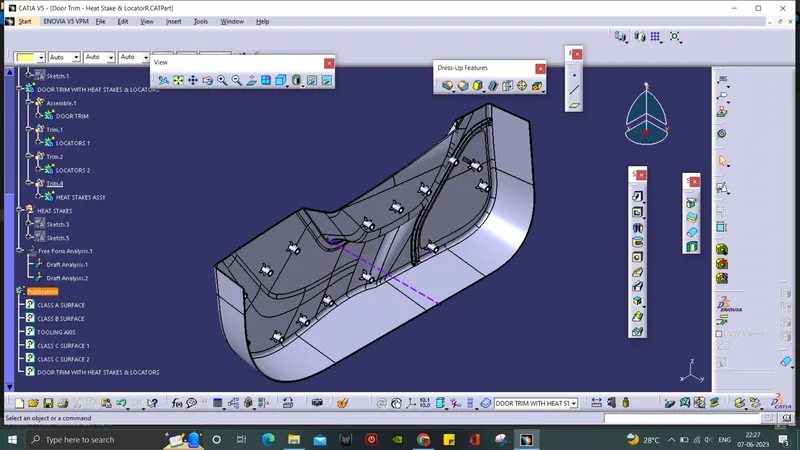
ISOMETRIC VIEW:
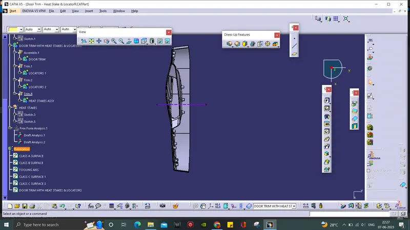
FRONT VIEW:
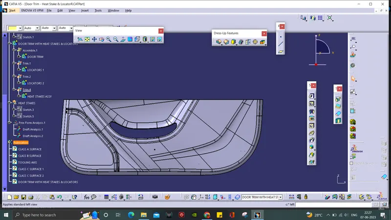
TOP VIEW:
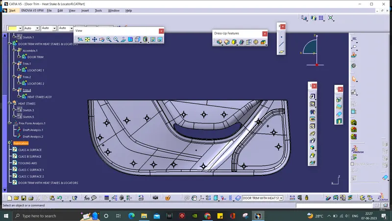
BOTTOM VIEW:
SIDE VIEW: