Week 9 - Challenge 3 - Bumper
BUMPER
AIM:
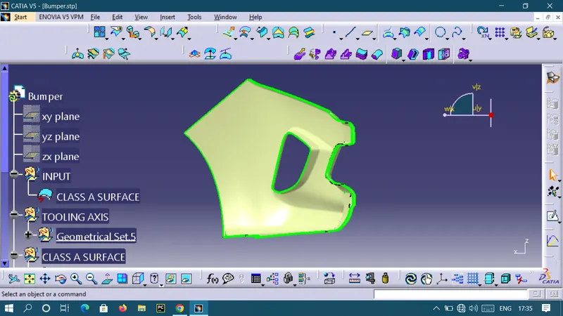
Create the Bumper Plastic component through the given Class-A surface. To begin with, the tooling axis for the given Class-A Surface should be created meeting the requirements of the draft angle and at the end perform the Draft analysis on the model. Take the Thickness of the component to be 3 mm.
Objective:
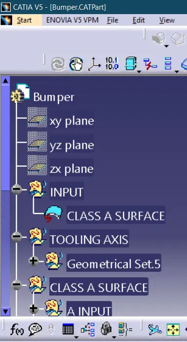
- Ensure Proper Tree Structure.
- Use the Close Surface feature to make a solid body from the surface.
- Publish the Tooling Axis, Class A, B, and C surface.
PROCEDURE:
CLASS A SURFACE:
In automotive design application Class A Surfaces are created on all visible exterior surfaces (ex; body panels, bumper, grill, lights etc.) and all visible surfaces of see-touch & feel parts in interior (ex: Dashboard, seats, door pads etc.).
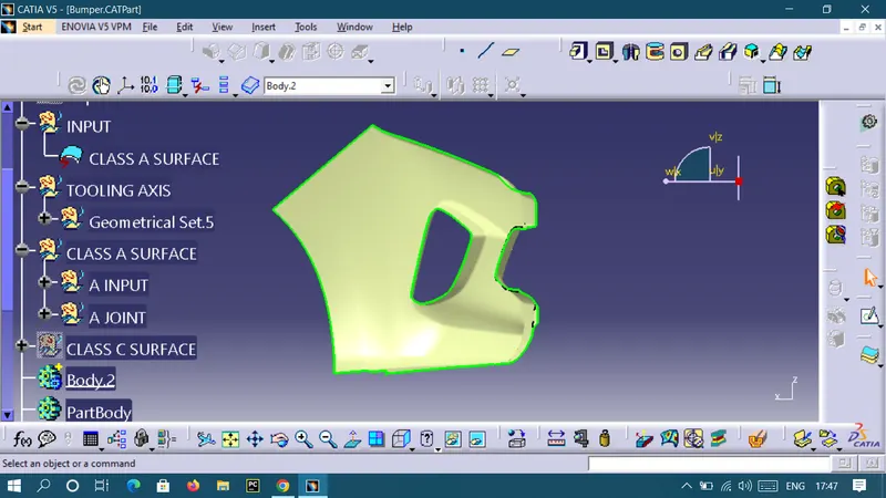
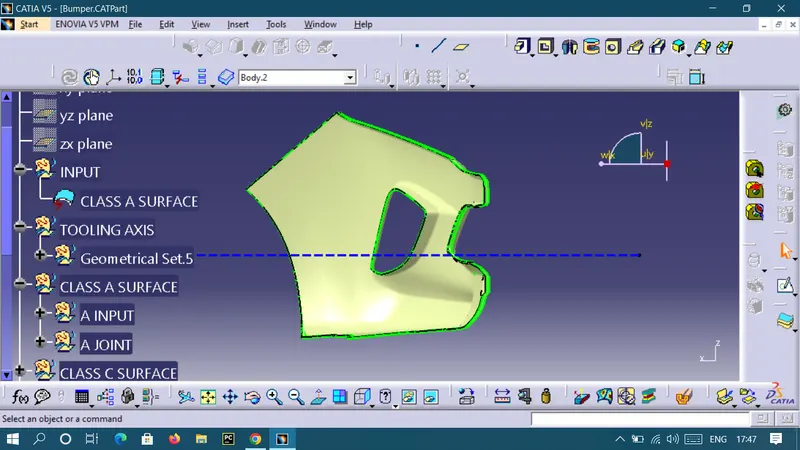
Creation of Tolling axis:
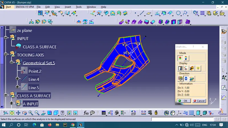
To create the tooling axis first we have to check the best suitable direction for tooling by using the compass. the x direction is suitable for creating the tolling axis because in the x direction most of the surfaces are clearing while performing draft analysis. Generally tooling axis is created using bisecting line method but here A line normal to the surface is created in the x direction and considered the tooling axis.
Draft Analysis :
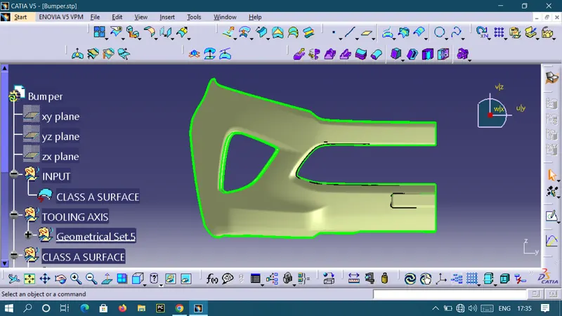
CREATION OF CLASS B SURFACE:
Class C Surface :
The Class C surface is the back side of a part of a surface that is permanently covered by another part.
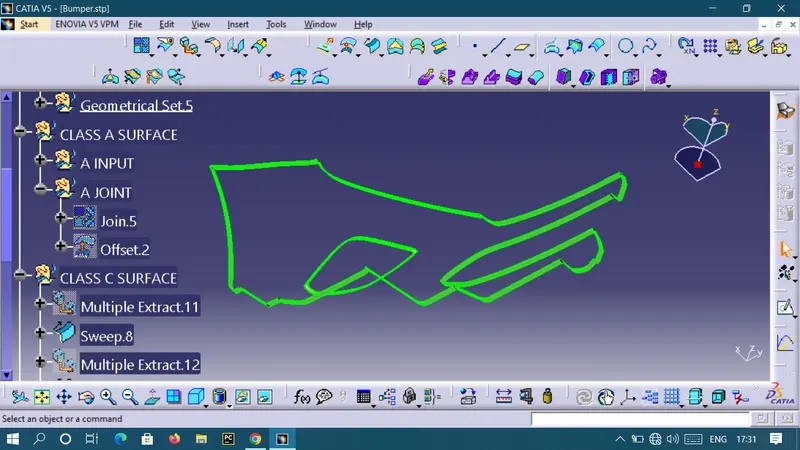
FINAL JOIN:
GEOMETRICAL TREE STRUCTURE:

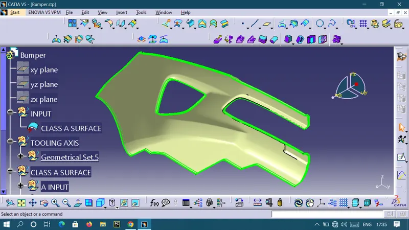
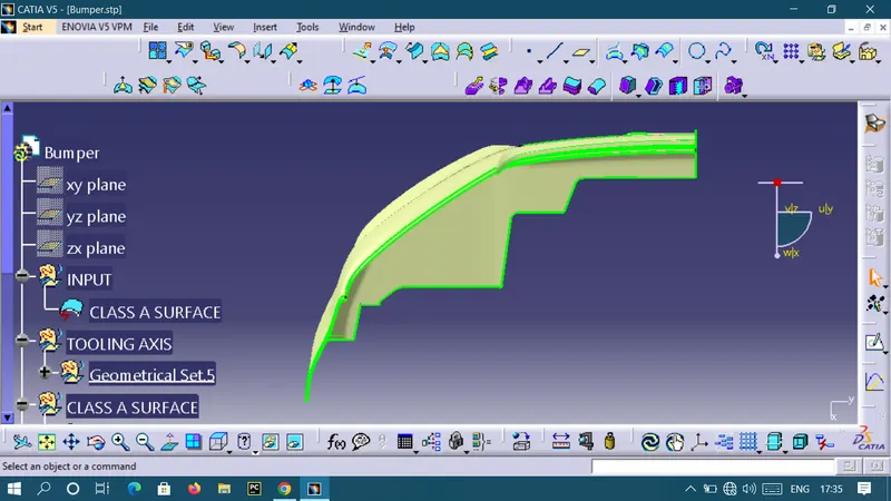
VIEWS
TOP VIEW
FRONT VIEW
SIDE VIEW
ISOMETRIC VIEW