Week 9 - Challenge 2 - Switch Bezel Design
SWITCH BEZEL
AIM :
To create a switch bezel Plastic Component through a given Class A Surface and perform Draft Analysis on the final plastic component.
Objectives:
Creation of Tooling Axis.
Creation of Class B and Class C surface.
Draft Analysis of Class A surface
Procedure:
CLASS A SURFACE :
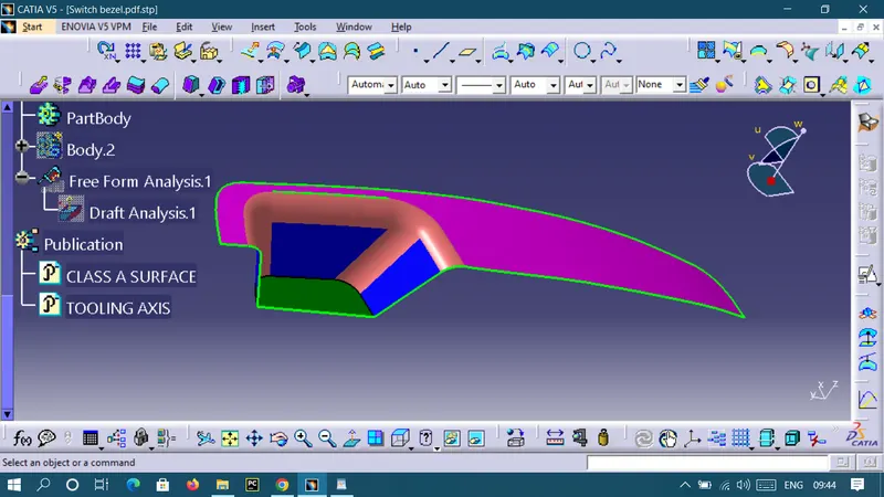
CLASS A is a given surface for to continue with the design process first we need to find out the tooling axis for the surface
TOOLING AXIS:
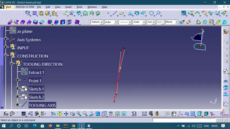
We need tooling aixs. So first take a intersection for CLASS A SURFACE and create a line in both sides, then create a bisecting line for that two lines and reference point take center point.
CLASS B SURFACE:
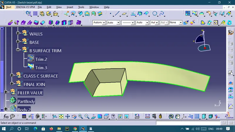
Now to create class B, we extract the surface from class A and unwrap them to get the original parent surface. That surface can extrapolate with point continuity and curvature. These surfaces are offset to the required thickness. After compensating, all surfaces are trimmed to the required shape. The required fillets are provided for the surfaces.
CLASS C SURFACE:
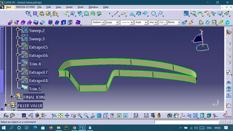
To create this surface, we extracted the boundary of class A using Multi-Extract and then converted into a smooth curve. Now this smooth curve is swept by a draft of 3 degrees in the draft direction.
FINAL TRIM:
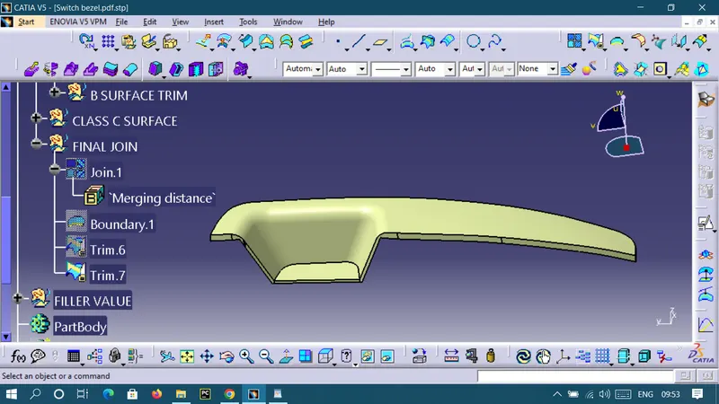
To ensure that there is no open boundary between class A and class C, we have used the join option to create a single body.
CLASS A + CLASS B + CLASS C
Thickness of the body:
Create a Closed thickness body surface
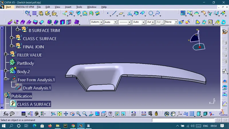
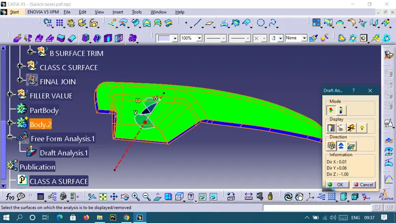
Draft Analysis for Surface A:
The analysis is done for 3degree draft.
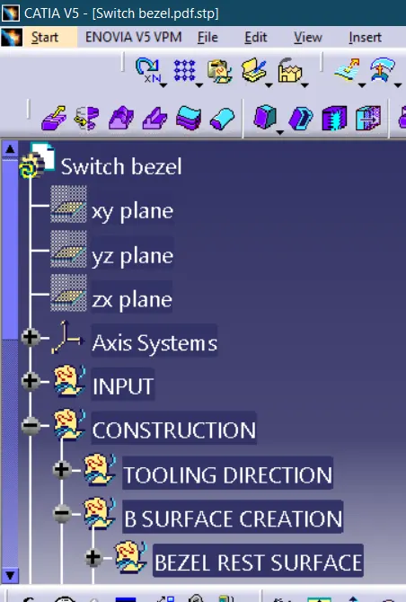
Geometrical Tree Structure:
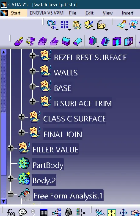
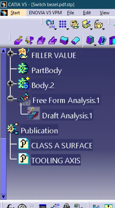
VIEWS
Top view
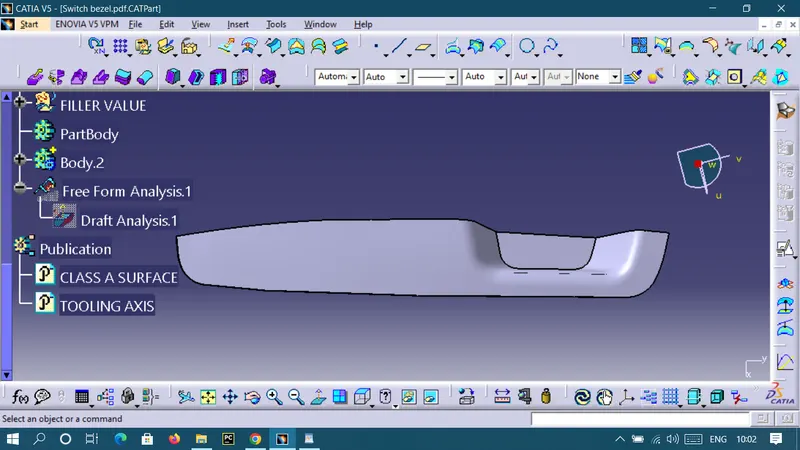
Side view
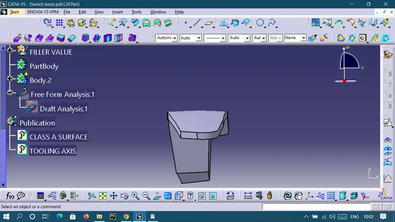
Front view
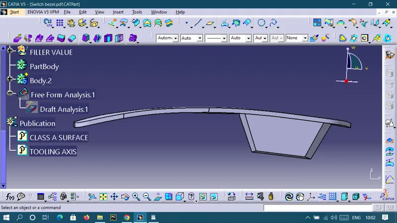
Isometric view
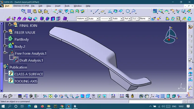
RESULT:
Thus, the plastic components of BASE BRACKET is created for thickness 2.5mm.