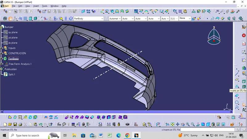
Week 9 - Challenge 3 - Bumper
AIM:
Create the Bumper Plastic component through the given Class-A surface. The tooling axis for the given Class-A Surface should be created meeting the requirements of the draft angle.
TOOLING AXIS
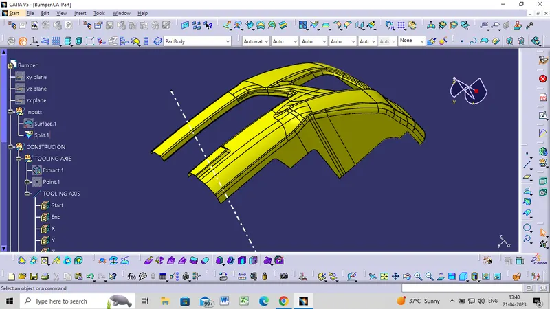
DRAFT ANALYSIS FOR CLASS A SURFACE
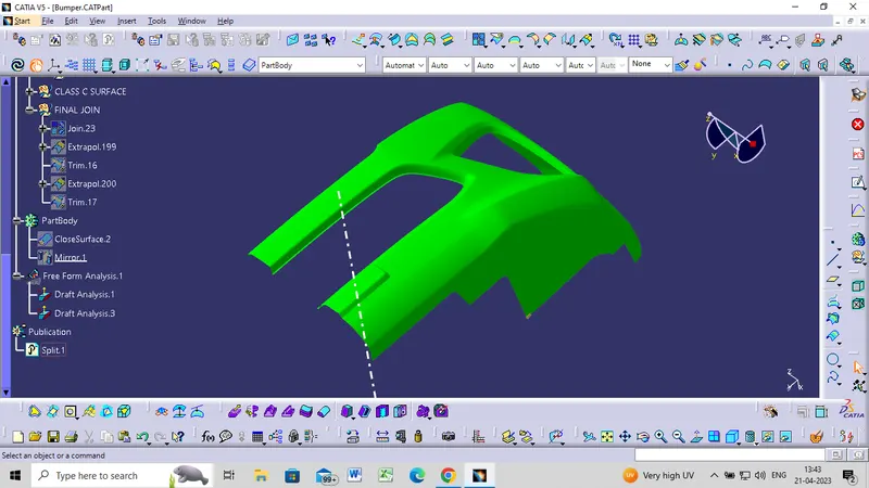
CLASS B SURFACE
- To create Class B Surface first offset the class A surface using offset command.
- The offset value is 3mm from the class A surface.
- This surface is not visible to the coustomer most of the times hence the surface finish is not as good as class A surface because it contains the ejector pins mark on it.
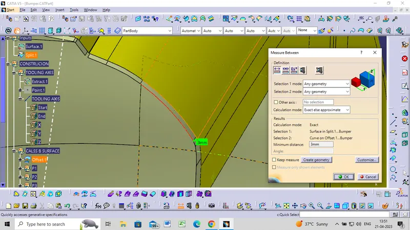
PATCH OF CLASS B SURFACE
PATCH 1
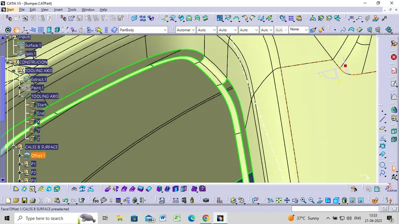
PATCH 2
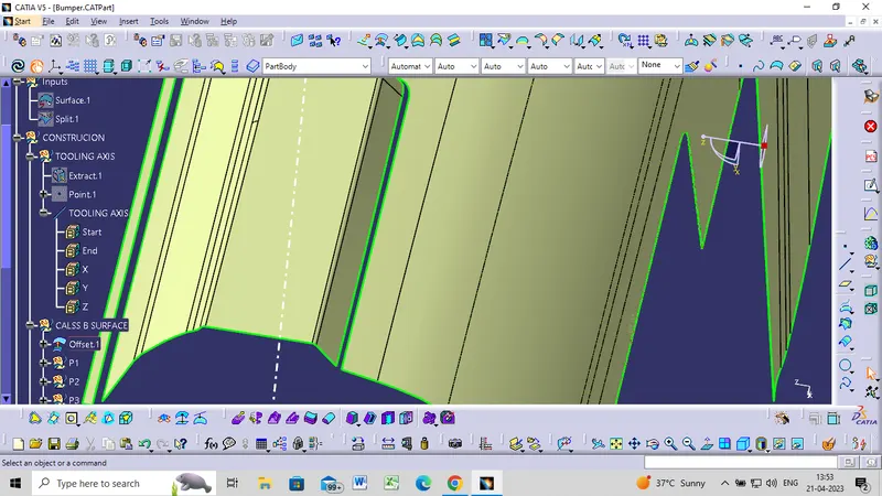
PATCH 3
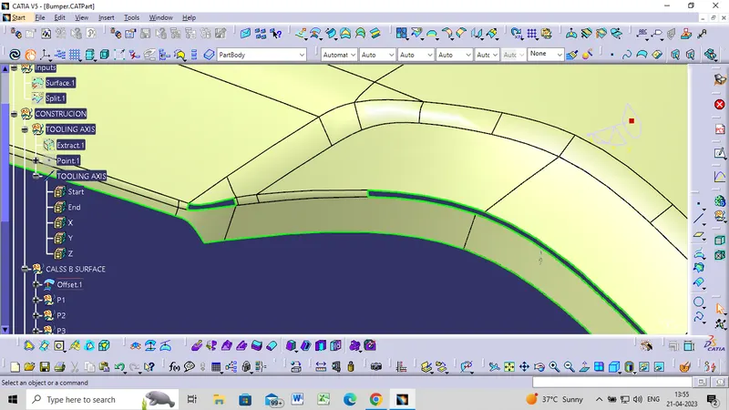
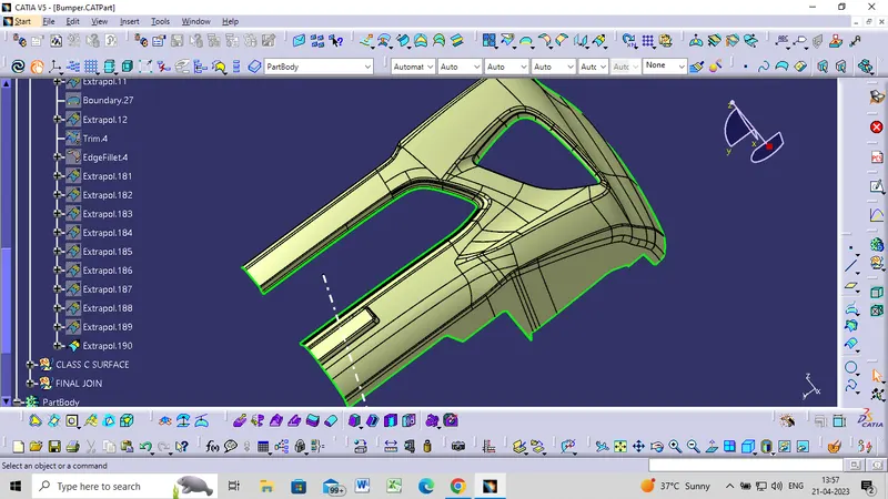
COMPLETE B SURFACE WITHOUT PATCHES
CLASS C SURFACE
- It is the surface which connects the class A surface and the class B surface .
- It can also be termed as the thickened surface .
- It is the surface which gives thickness to the designed component.
- But in this model the class c surface is perpendicular to tooling axis and parallel to core and cavity, therefore the class c surface is created 90 degree to the extracted boundary surface of class A surface.
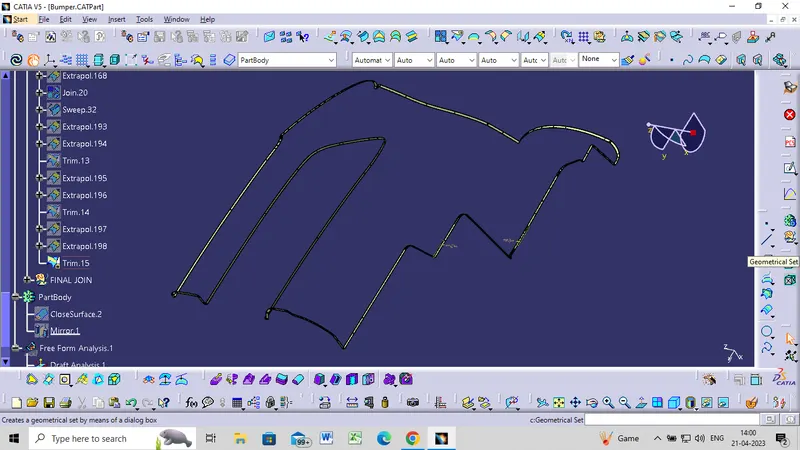
FINAL TRIM
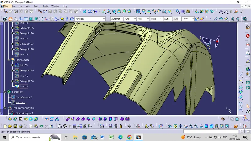
CLOSE SURFACE
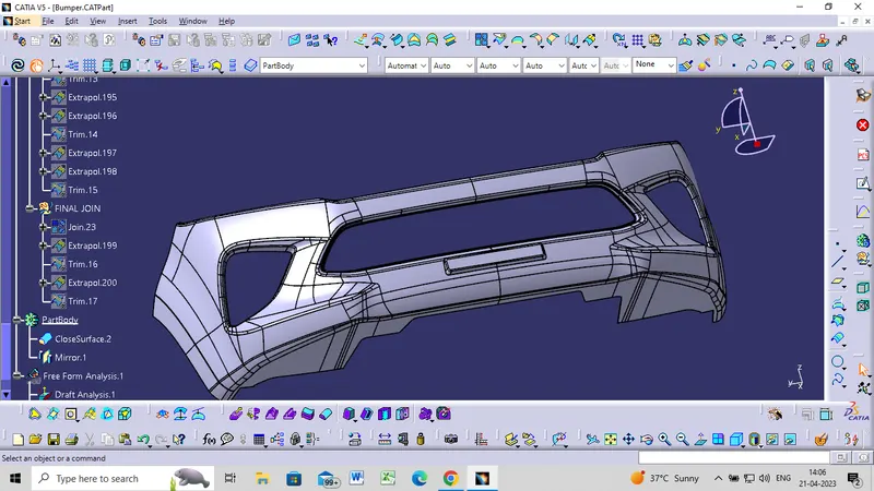
DRAFT ANALYSIS
- Draft analysis of the surface is carried to check if the surface or part can be manufactured with the required draft angle.
- Draft angle is needed for the component to clear the core and cavity surface as it would have shrunk towards the center while cooling.
- The draft angle in this design is 3 degrees. As A surface is a single surface there won't be much difference in color.
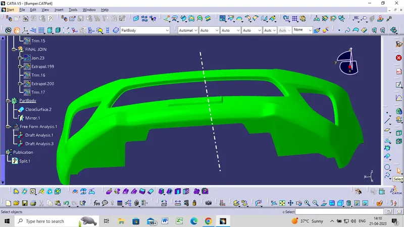
TREE STRUCTURE
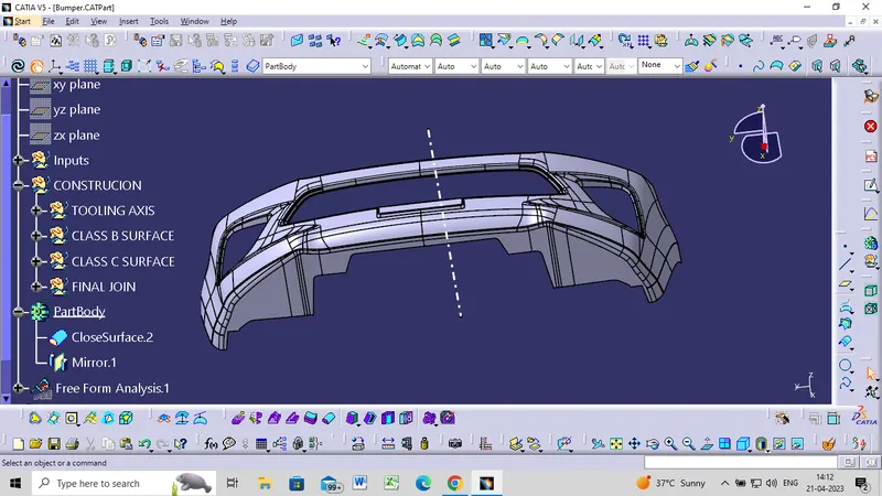
FRONT VIEW
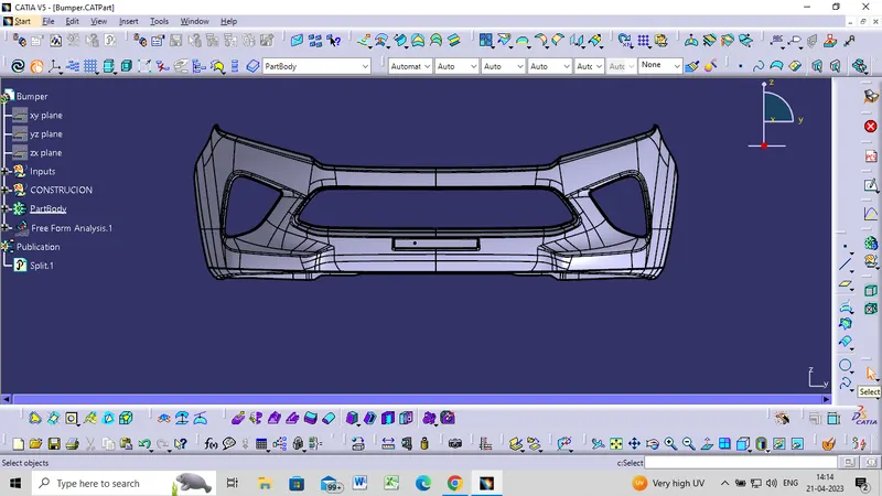
TOP VIEW
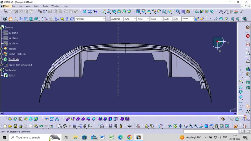
SIDE VIEW
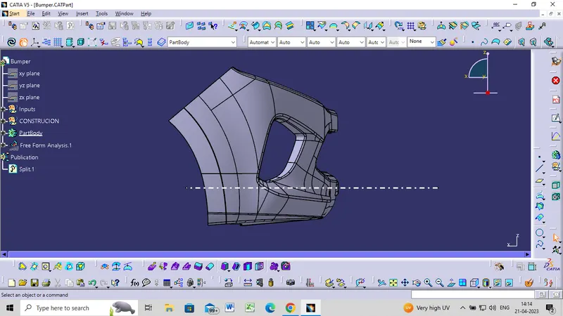
ISOMERTIC VIEW