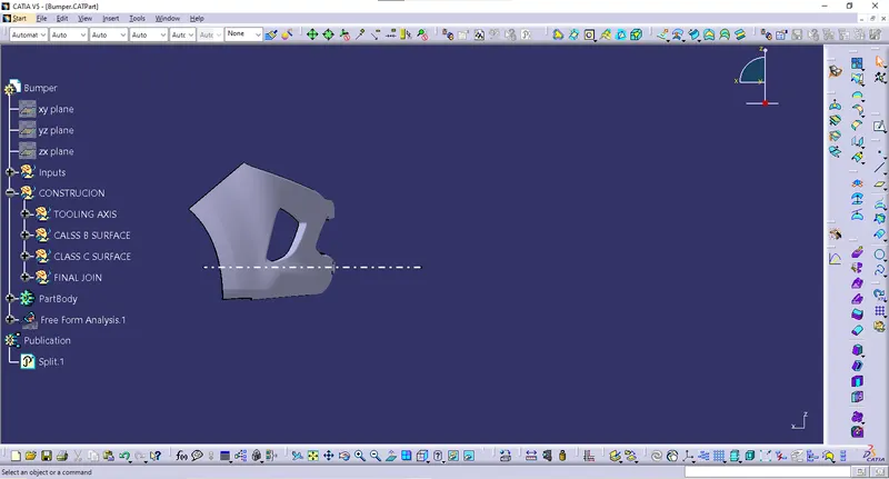
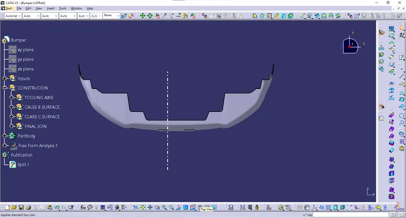
Week 9 - Challenge 3 - Bumper
BUMPER OF A CAR
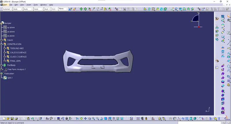
Creating the BUMPER plastic component through the given Class-A surface. To begin, the tooling axis for the given Class-A Surface should be created.
TOOLING AXIS CREATING MEATHOD
1 - With respect to the axis system; that is along the axis x , along axis y , along axis z.
2 - Normal to surface.
3 - Bisecting method
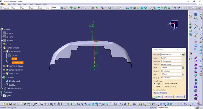
In this model the tooling axis is created along the X-axis in the center of grill hole on the class A surface.
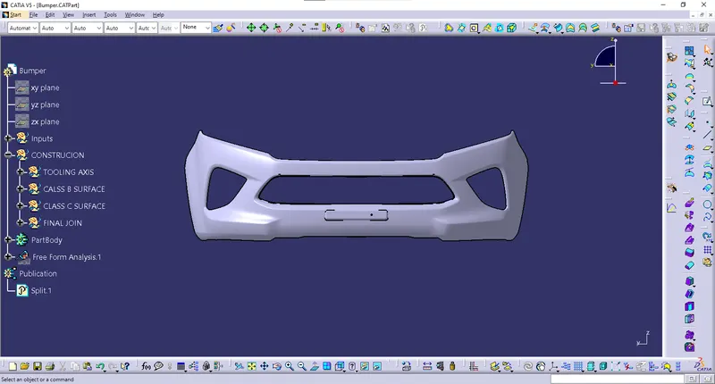
CLASS A SURFACE
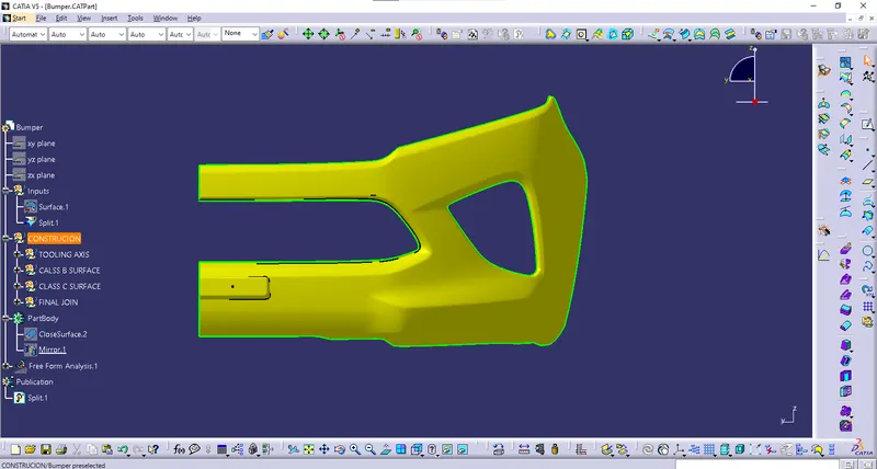
Class A surface means those surfaces which are visible in a product either interior or exterior. It describes the final production surface data for the aesthetic parts of the car.
The below image shows the Class A surface :
CLASS B SURFACE
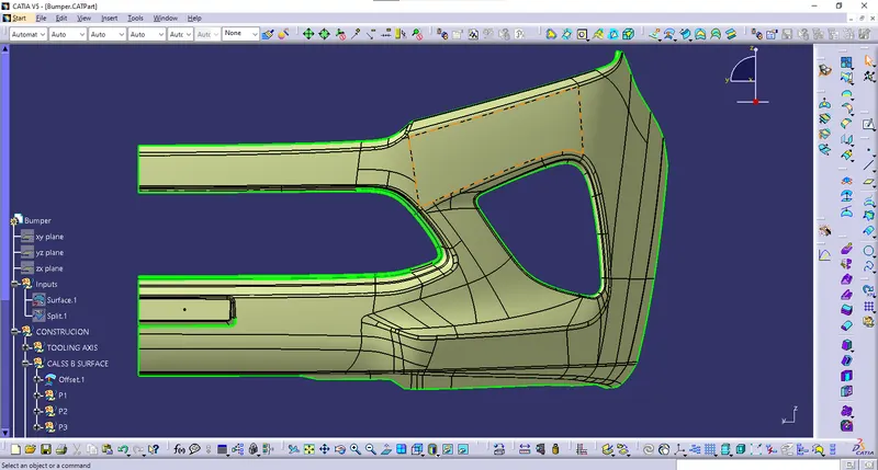
Class B surfaces are the secondary surfaces that you can see sometimes, but are less important . This surface is not visible to the coustomer most of the times hence the surface finish is not as good as class A surface because it contains the ejector pins mark on it.
CREATION OF CLASS B SURFACE
- To offset the class-A surface along 3mm for to create a B- SURFCAE.
- Surface Gaps can be filled by using a fill tool and multi sectional tool
SOLVED PATCHES IN CLASS B SURFACE
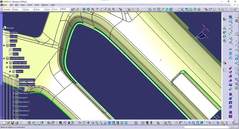
PATCH 1 BEFORE
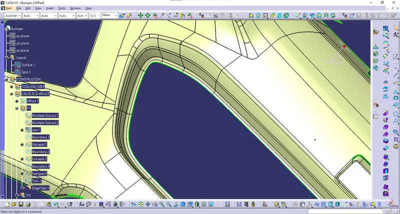
PATCH 1 AFTER
PATCH 2 BEFORE
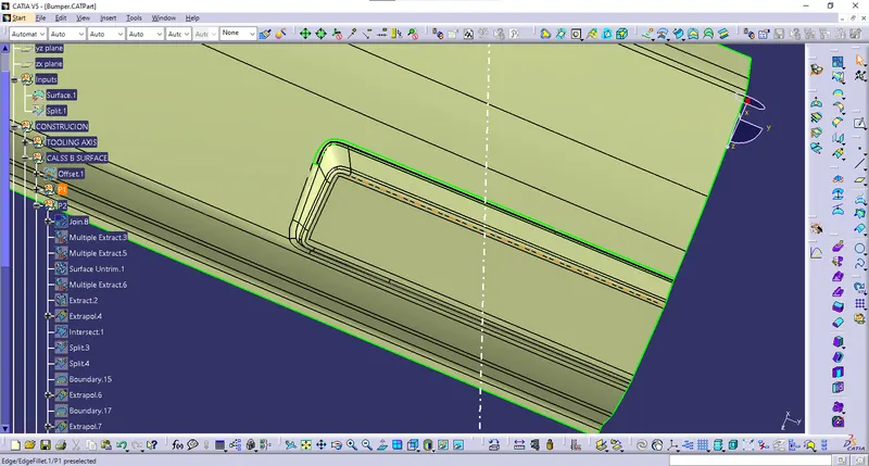
PATCH 2 AFTER
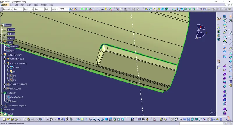
PATCH 3 BEFORE
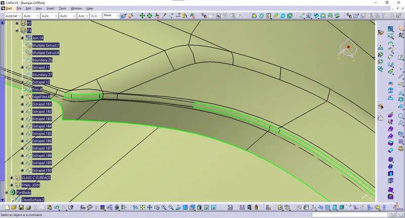
PATCH 3 AFTER
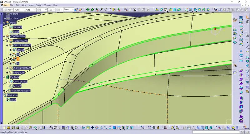
CLASS C SURFACE
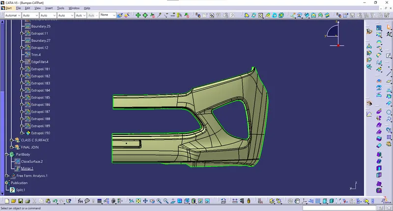
It is the surface which connects the class A surface and the class B surface . It can also be termed as the thickened surface . It is the surface which gives thickness to the designed component. But in this model the class c surface is perpendicular to tooling axis and parallel to core and cavity, therefore the class c surface is created 90 degree to the extracted boundary surface of class A surface.
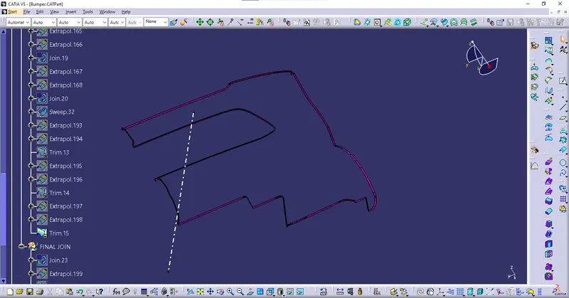
DRAFT ANALYSIS
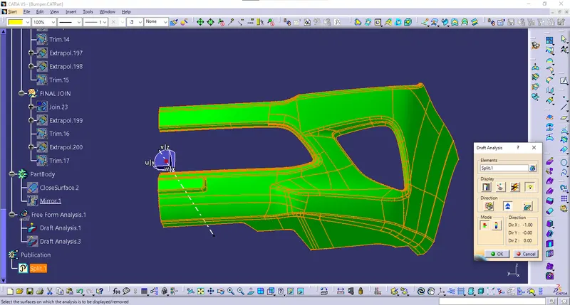
DRAFT ANALYSIS ON CLASS SURFACE
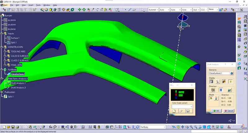
DRAFT ANALYSIS ON FINAL COMPONENT
TREE FEATURE
VARIOUS VIEWS OF THE FINAL COMPPONENT