Week 9 Challenge
Hi,
Here I'm submitting the sliders & inserts creation for the CPU FAN CASE model.
Procedure followed for slider 1 creation of CPU FAN CASE model :
- First, I have started with a rectangular sketch in core block of covering circular undercut for creating first slider.
- Then using the sketch & the sketched surface I have splitted the block using 'split' tool.
- Then I have cutted out the extra projections in the splitted block & created a base for it.
- Then I converted the circular entity for the slider & extruded it in slider block.
- And created the same chamfer 0.75mm as in the part in the splitted block for slider.
- Then I created fillets for the slider.
- Finally I have save it as a new parasolid part & insert it into the assembly.
- And saved the part as slider 01.
- Then inserting the slider into the core & cavity blocks individually for creating the cuts according to the slider block created using 'combine' tool.
- For creating bolts & washers, I have created extra stepped cut using 'cut-extrude' tool.
- And I have created the tapped holes on the path of the cut using 'hole-wizard' tool & inserting the bolt & washer parts & mated it to the holes respectively.
- And I have created the slider locking path in the slider & in the core block by arriving the 16mm travel distance.
- Finally, I have assigned yellow colour to the block.
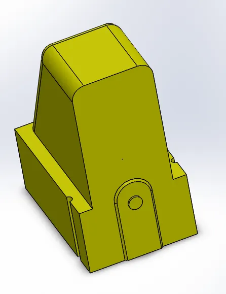
Procedure followed for slider 2 creation of CPU FAN CASE model :
- First, I have started with a rectangular sketch in cavity block of covering 2 square undercuts & side ribs for creating second slider.
- Then using the sketch & the sketched surface I have splitted the block using 'split' tool.
- Then I have cutted out the extra projections in the splitted block & created a base for it.
- Then I converted the square entities for the slider & extruded it in slider block.
- Then I created fillets for the slider.
- Finally I have save it as a new parasolid part.
- Next, for creating another part of the slider in the core block, splitted the block by convering the same sketch using 'split' tool.
- Then save the slider as a new parasolid part.
- Then I have insertsed both parasolid parts into a new part in the assembly & combined it using 'combine' tool.
- Then inserting the slider into the core & cavity blocks individually for creating the cuts according to the slider block created using 'combine' tool.
- For creating bolts & washers, I have created extra stepped cut using 'cut-extrude' tool.
- And I have created the tapped holes on the path of the cut using 'hole-wizard' tool & inserting the bolt & washer parts & mated it to the holes respectively.
- And I have created the slider locking path in the slider & in the core block by arriving the 30mm travel distance.
- Finally, I have assigned yellow colour to the block.
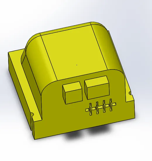
Procedure followed for insert 1 & 2 blocks creation of CPU FAN CASE model :
- First, creating a plane 20mm offsetted from base of the model in core block.
- And I have increased the core block thickness to 50mm more for ejector pin provision.
- Then i have created a sketch covering the deep undercut in the core block.
- Using the sketch & the plane created, I have splitted the part using 'split' tool.
- Following the same procedure, created the insert 2 block.
- And saved both the blocks as a new part & inserted into the assembly.
- Finally, I have assigned blue colour to the blocks.
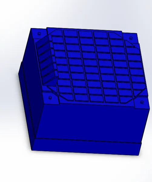
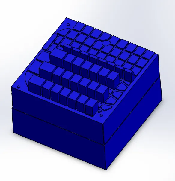
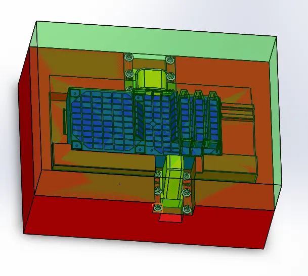
And, here I have submitted the sliders & inserts creation in the challenge.
Thanks,
Deepak kumar A S.