Week 12 Challenge
Hi,
Here I'm submitting the ejector pins & plates, runner & gate system, air vents, cooling channels creation for the PLASTIC KNOB model.
Procedure followed for ejector pins, plates creation of PLASTIC KNOB model :
- First, I have started with ejector pin sketch of diameter 6 on the top face of the core steel.
- And extruded it upto the part surface & 250 offset from the same surface.
- Then created ejector pin reliefs on the core block of 6.95 diameter for all the holes & extruded cut it to 84mm.
- Then I created ejector plate on the top of the ejector pin of 10mm thickness & offsetted 45 each side on the core block.
- Then created ejector end plate on the top face of the ejector plate of 15mm thickness and of the same dimension.
- And I created an ejector pin lock of 10 diameter and a flat face for orientation on all the pins.
- And the same sketch offsetted on the ejector plate of 12mm and the same flat face sketch & used ‘extruded cut’ on it.
- Finally, I have given respective colours to the ejector pins, plates.
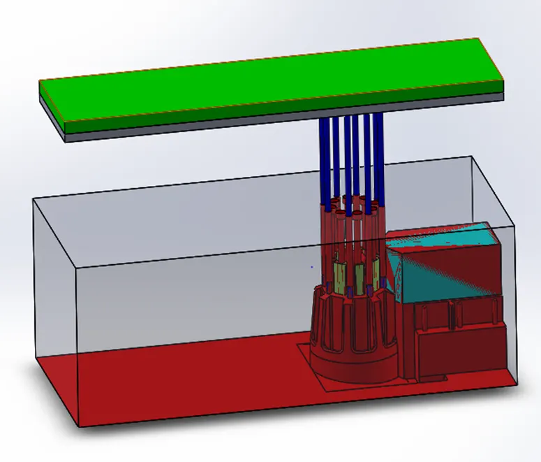
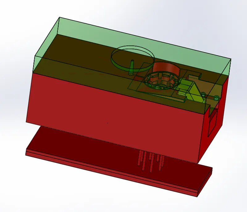
Procedure followed for runner & gate system creation of PLASTIC KNOB model :
- First, I have created the runner path on the cavity block of 120 diameter on the origin of the block & used ‘extruded cut’ of 12mm.
- Then for the runner path, I have created diameter 5.8 on the cutted surface and the draft angle of 3.5 degrees outwards through all.
- And converted the drafted end diameter to the top face of the core block & used ‘extruded cut’ of 5mm on it.
- Then for the gate location, I have created a line on the core block nearby the previous cut & extruded it to 4mm x 4.5mm till the opening of the part creation.
- And I have drafted the side faces of the block to 10 degrees inwards.
- Then I have filletted the bottom edges of the block.
- Then I have created another triangular sketch to the front of the block & extruded it to 0.5mm.
- Then filletted its front edges & combined both the blocks using ‘combine’ tool.
- Finally, subtracted the block with the core block using ‘combine’ tool.
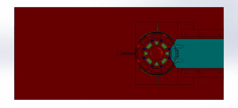
Procedure followed for air vents creation of PLASTIC KNOB model :
- First, I have offsetted the outer circular edge of the model on the core block.
- Then extruded it 2mm to some extend on both sides.
- And splitted it using ‘split’ tool & consumed the cut body.
- Then moved the bottom face of it to 1mm using ‘move face’ tool.
- And filletted the bottom edges.
- Then created an inner block to it of a diagonal shape upto its same surface.
- And moved its face to 0.02mm on the bottom using ‘move face’ tool.
- And combined both the blocks using ‘combine’ tool.
- Then created a path for the air vent as a sketch on the perpendicular side of the above features, and extruded it upto the same surface.
- And filletted its bottom edges.
- Then combined these two blocks using ‘combine’ tool.
- Then I have mirrored the all the block on the opposite side.
- Then, finally combined both the blocks with the core block using the same ‘combine’ tool.
- Finally given respective colours to the air vent paths.
Procedure followed for cooling channels creation of PLASTIC KNOB model :
- I have created the cooling channels on the core block.
- I have used hole wizard to create the path for the cooling channels.
- I have used M10 Socket Head Cap Screw for the channel paths.
- I have created the holes on all the faces by merging the holes for the paths.
- I have assigned the paths little away from the part section, to avoid intersections.
- Finally, given different colours to the paths.
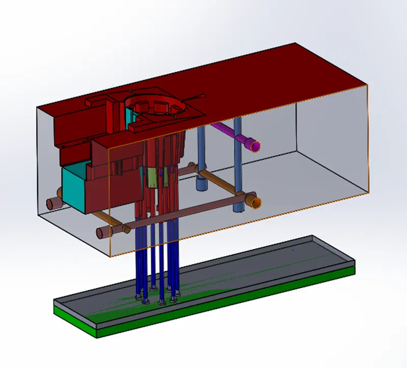
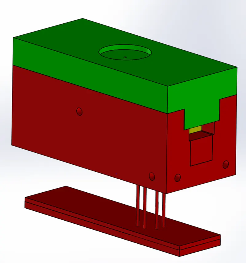
- Finally, saved the core, cavity, slider individual parts of it into its separate assembly.
And, here I have submitted the ejector pins, plates, runner, gate path, air vents, colling channels creation in the challenge.
Thanks,
Deepak kumar A S.