Project 1
Hi,
Here I'm submitting my 1st project on Table fan base model.
Procedure followed for core & cavity surface creation of TABLE FAB BASE model :
- First, I made the Draft analysis for the given component & verified the the draft angles on the yellow region.
- Then, I scaled the component to 1.006(0.6%) as assumed the product as ABS.
- Then I created the parting line for the given component by selecting the edge manually.
- And I created the shut-off surface, for the open cut out present in the product.
- Then I created planar surface along the origin & trimmed the inner surface to create the ‘parting surface’.
- Then I created a copy of the parting surface using ‘move/copy bodies’ tool.
- And I perform ‘knit surface’ with one of the parting surface and cavity surface & another parting surface and core surface respectively.
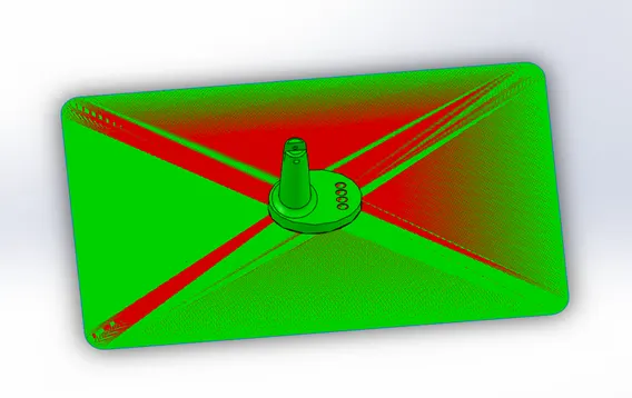
Procedure followed for core & cavity block creation of TABLE FAN BASE model :
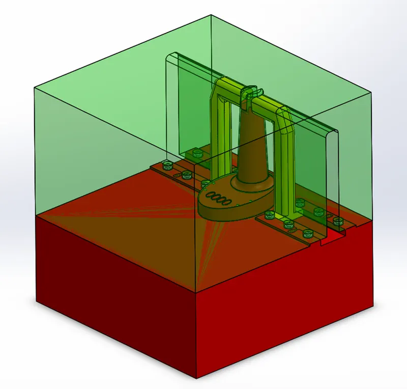
- For the mold block creation, I inserted the surface model into a new assembly.
- Then I'm aligned the sprue location to the assembly origin & fixed it.
- Then I have created a sketch of a rectangle of 500mm X 500mm in a new part as core steel.
- Then I created a copy of the parting surface using 'offset surface' tool.
- And I extruded the sketch of the core steel part up to 300mm on both sides.
- Then I have used 'cut with surface' tool to create 3d profile on the core block.
- For the cavity steel part, I used 'convert entities' as the same sketch created in core steel part.
- Then I created a copy of the parting surface using 'offset surface' tool.
- And I extruded the sketch of the core steel part up to 300mm on both sides.
- Then I have used 'cut with surface' tool to create 3d profile on the cavity block.
- Finally, I have assigned the respective colours to the core & cavity blocks individually.
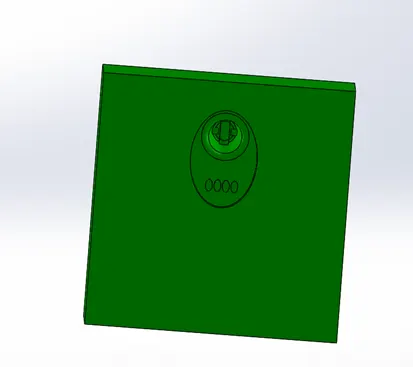
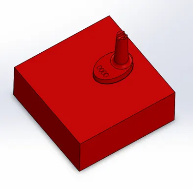
Procedure followed for slider 1 creation of TABLE FAN BASE model :
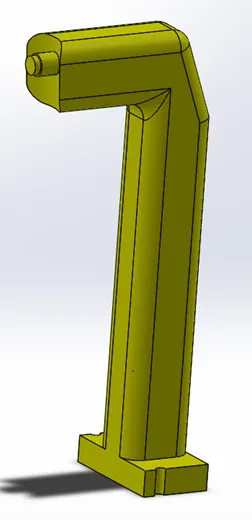
- First I have started with ‘convert entities’ for the through hole & using ‘split’ tool to create slider part in the core block.
- Then I have created a rectangle on the top plane & extruded it for slider base.
- And created a sketch above the rectangular slider base of 40mm x 35mm & extruded it to 260mm.
- Then for creating horizontal path of the slider, extruded the same sketch up to the surface of the part.
- Then created the extra projections on the part by extruding it.
- And created ‘fillets’ on the slider edges.
- Finally, I have saved it as a Parasolid file.
- Then inserting the slider into the core & cavity blocks individually for creating the cuts according to the slider block created using 'combine' tool.
- Then inserted the slider into the assembly and save it as ‘slider 01’.
- For creating bolts & washers, I have created extra stepped cut using 'cut-extrude' tool.
- And I have created the tapped holes on the path of the cut using 'hole-wizard' tool & inserting the bolt & washer parts & mated it to the holes respectively.
- And I have created the slider locking path in the slider & in the core block by arriving the 90mm travel distance.
- Then I have mated M6 bolts and washers accordingly.
- Finally, I have assigned yellow colour to the block.
- And I have created external cutouts for the slider movement along the core & cavity blocks.
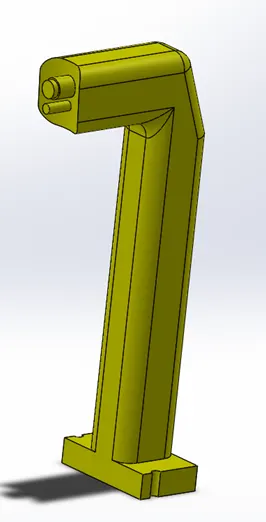
Procedure followed for slider 2 creation of TABLE FAN BASE model :
- First I have started with ‘convert entities’ for the through hole & using ‘split’ tool to create slider part in the core block.
- Then I have created a rectangle on the top plane & extruded it for slider base.
- And created a sketch above the rectangular slider base of 40mm x 35mm & extruded it to 260mm.
- Then for creating horizontal path of the slider, extruded the same sketch up to the surface of the part.
- Then created the extra projections on the part by extruding it.
- And created ‘fillets’ on the slider edges.
- Finally, I have saved it as a Parasolid file.
- Then inserting the slider into the core & cavity blocks individually for creating the cuts according to the slider block created using 'combine' tool.
- Then inserted the slider into the assembly and save it as ‘slider 02’.
- For creating bolts & washers, I have created extra stepped cut using 'cut-extrude' tool.
- And I have created the tapped holes on the path of the cut using 'hole-wizard' tool & inserting the bolt & washer parts & mated it to the holes respectively.
- And I have created the slider locking path in the slider & in the core block by arriving the 90mm travel distance.
- Then I have mated M6 bolts and washers accordingly.
- Finally, I have assigned yellow colour to the block.
- And I have created external cutouts for the slider movement along the core & cavity blocks.
Procedure followed for ejector pins creation of TABLE FAN BASE model :
- For creating ejector pins in the core block, created 6mm diameter pin using ‘core’ tool.
- Then created reliefs for ejector pins & saved it as a new Parasolid file.
- Then insert it as new part into the assembly & save it as ‘ejector pin’.
And here I have submitted my 1st project.
Thanks,
Deepak kumar A S.