Week 9 Challenge
CPU FAN CASE
AIM- To create core and cavity block of the CPU fan case model with proper dimensions and also create slider for the undercut and create insert.
As there was undercut present in the model therefore, we create the slider and for slider we create washer and locking mechanism.
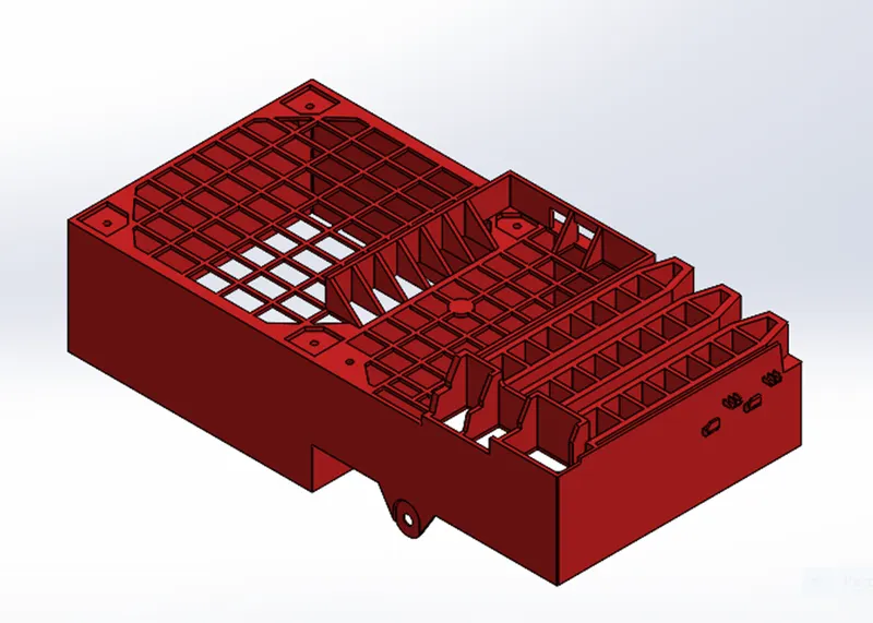
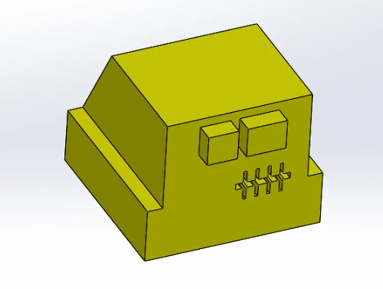
Given model
Mold Tools used
TOOLING DIRECTION- The direction in which the mold blocks move the cavity or the direction in which the component eject from the mold is called tooling direction.
The selection of tooling direction always be minimum number of undercuts is formed and the overall difficulty of the mold reduces.
DRAFT ANALYSIS- At first, we check the model adequate draft are provided or not. if not then we tell the product team that they should provide the adequate draft where it needed.
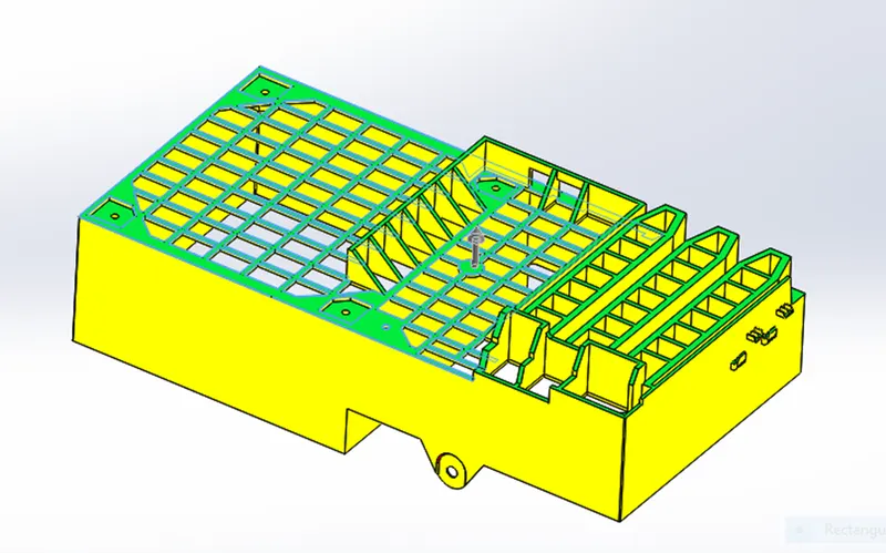
SCALE- scale the model by a specified factor based on the material provided. Assume the, material for the model as ABS (shrinkage -0.6%) the scale value is determined (0.6/100) +1=1.006.
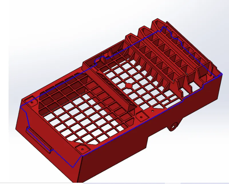
PARTING LINE- The parting line is where the two halves of the mold meet around the parameter of the part. All parting lines need to seal properly when the mold is clamped in a molding machine. The form of parting line depends on the specific situation of the plastic part, but generally there are several types: vertical stepped, inclined, curved and integrated parting lines.
Parting line separates the core and cavity surface.
For creating parting line we need some edge that’s why we create some sketch and split it then create parting line.
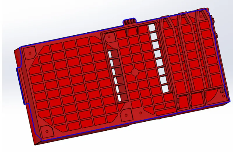
SHUT- OFF SURFACES- Creates mold shut-off surfaces by creating a surface patch along a parting line or edges that formed a continuous loop. these prevent any through holes in the cavity or core surfaces bodies.
To cut a tooling block into two pieces, you need two complete surfaces (a core surface and a cavity surface) without any through holes. Shut-off surfaces close up the through holes. You create shut-off surfaces after you create the parting lines.
PARTING SURFACES- use ruled surface for create the parting surface. Creating edges in the core cavity surface uses split command to create it. We create sketch in the front plane draw line and then split it select the faces where we project the line.
Using those edges, we create ruled surface after creating ruled surface we using lofted surface and using knit to merge together.
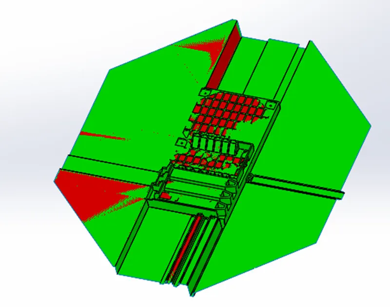
CORE&CAVITY SURFACE- Go to direct editing option move/copy bodies tool copy of parting surface and knit with core and cavity surface.
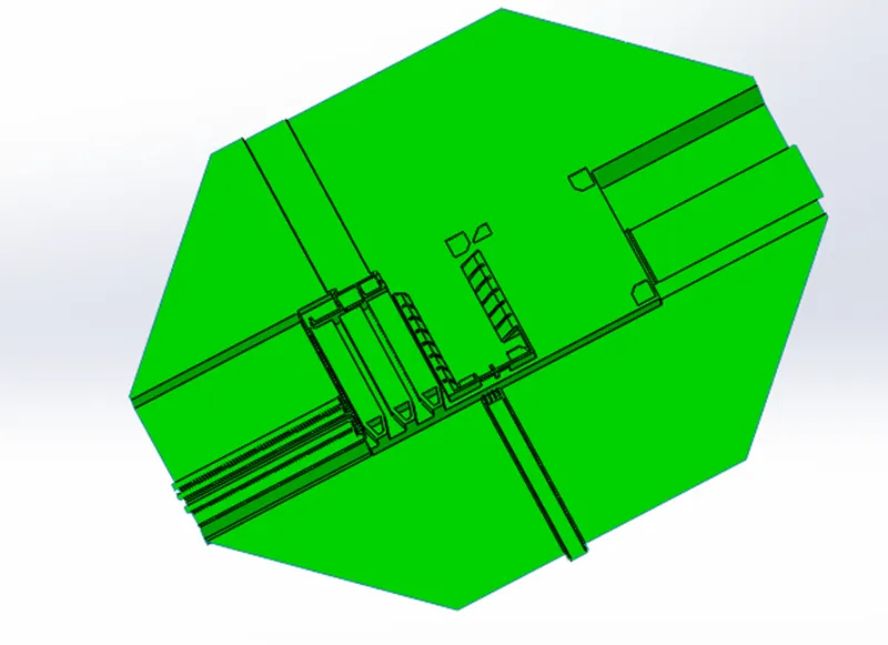
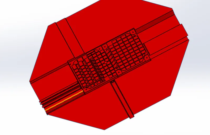
CORE&CAVITY BLOCK- create an assembly create new part one is core and another is cavity. the core and cavity block are created as individual part in assembly by inserting the component as core and cavity surface created for car door bezel.
The core block is created using core surface. there will be 2 block internal and external block which are created considering minimum distance between mold and outer edge and base of the slider these two-block due to a curvature in parting line and these two-block act as single block.

The cavity block is created using cavity surface there also 2 block internal and external block which are created considering minimum distance between mold and outer edge and base of the slider these two-block due to a curvature in parting line and these two-block act as single cavity block.
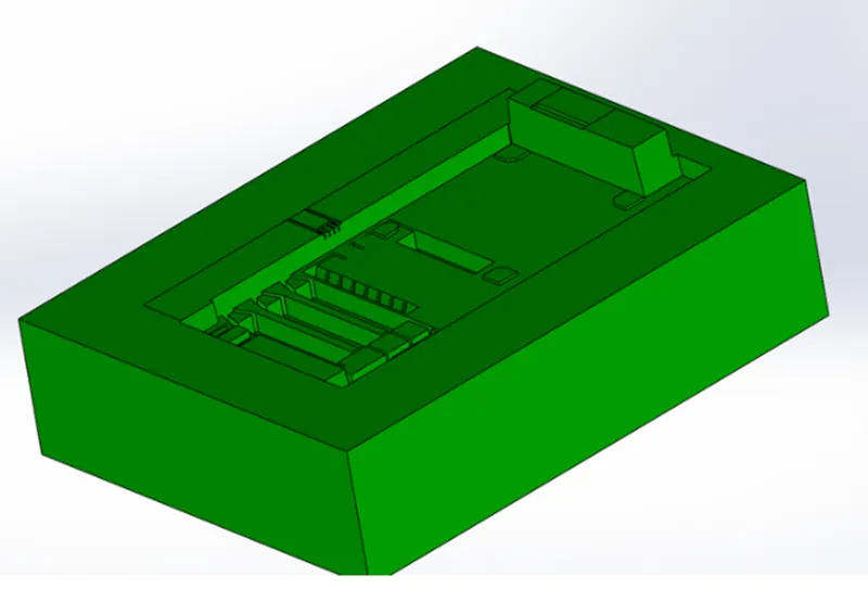
During mold design of CPU fan case, we can clearly see that there was undercut present in the model to optimize the undercut slider will be used.
Slider direction will be perpendicular to the directional pull which will be horizontal these are separable from the core and cavity block as the slider are movable.
Slider- Due to the special requirements of a product, the mold release direction of a particular part may not be consistent with the mold opening direction of the injection molding machine (product undercut), the slider, also known as slide, is a mold mechanism that is developed to solve the issues with the undercut. The basic principle is to turn the vertical movement of mold opening / closing into a horizontal motion. In order to cope with the situation that the undercut is located in the core or cavity, different structural forms are developed.
Feature used for creating slider-
Reference plane – This command is used for creating plane and axis. the reference plane is created perpendicular to the line of undercut region.
Sketch – using this command we create a new sketch on created new plane.
Convert entities- You can create one or more curves in a sketch by projecting an edge, loop, face, curve, or external sketch contour, set of edges, or set of sketch curves onto the sketch plane.
Split- it is available in feature tab use to split the body into two pieces along the sketch based on application.
Cut extruded- used to remove material from a solid body along the sketch in which direction we need based on application.
Boss Extruded- to add material from a solid body along the sketch in which direction we need based on application.
Move face-It is available in mold tool tab used to move face of a solid body.
Move/copy bodies- It is available in mold tool used to move copy and rotates solid body or surface bodies.
Combine- it is available in mold tool tab used to add, subtract bodies.
DELECT/KEEP BODY- It is available in the mold tool tab to keep or delete a solid body or surface body.
PROCEDURE STEPS FOR CREATING SLIDER-
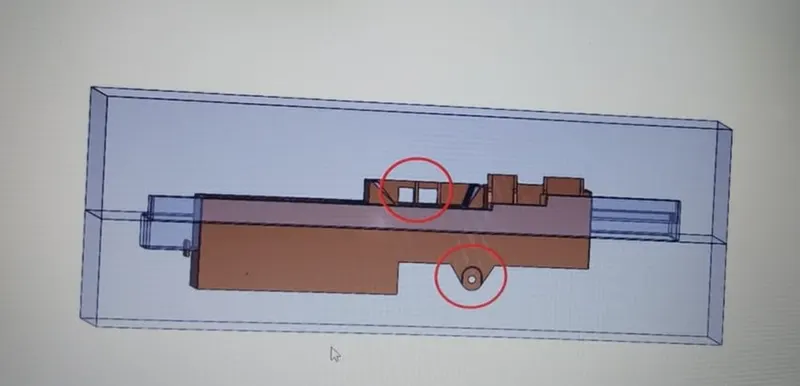
Step 1- for creating slider first of all open the core block and select the face near the undercut and create a sketch make a rectangle that cover the undercut. And using split option make the slider.
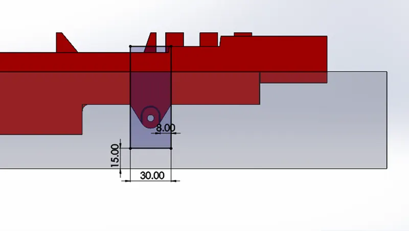
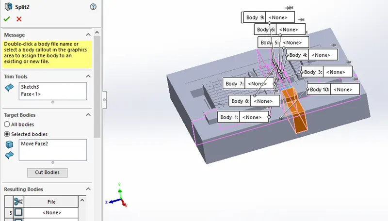
STEP 2- create another sketch on the slider created and extruded it. give the proper chamfer for the feature to match properly. Add more material to cover the hole. fixing the shape for adding material create sketch and extruded it.
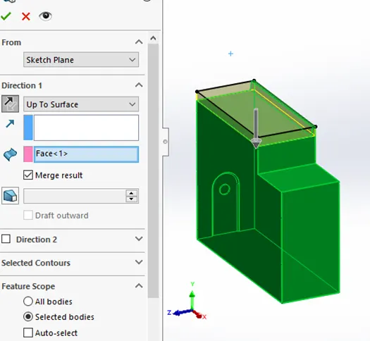
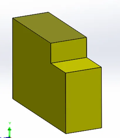
STEP 3- creating wedge for the slider create sketch on side face and cut extruded it.
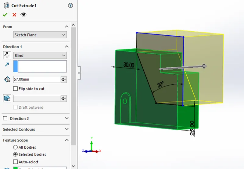
STEP 4- to make collar for the slider adding material at bottom, after that reduce the extra portion.
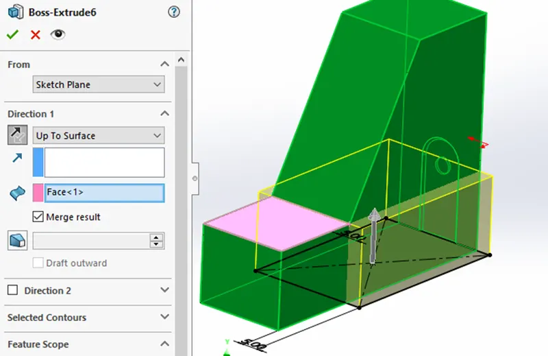
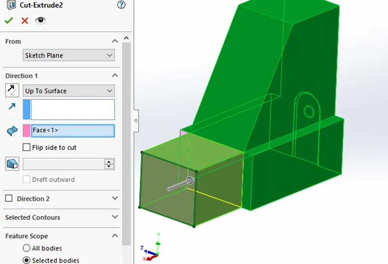
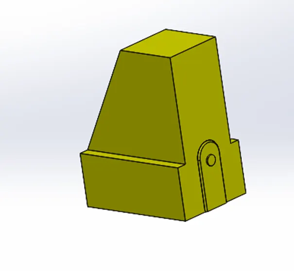
Save the part file as Parasolid file, and open assembly create a part name slider and save it. imported the slider .
Now edit the core part and go to direct editing combine subtract the slider part from the main part.
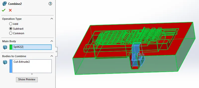
now edit the core block accordingly to slider
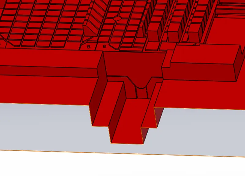
Edit the cavity block for the slider
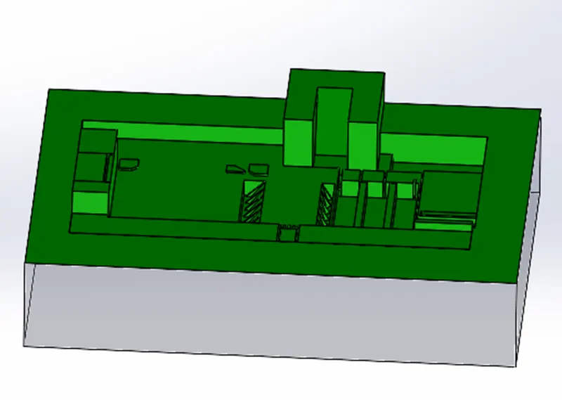
Creating another slider for undercut
The slider is created using split option making the sketch as the profile of the undercut on plane which sketch is made.
These sliders are modified such that washer and locking mechanism will be correctly designed.
The core and cavity block are made according to the shape of the slider after creating all mechanism using combine command.
after reducing of slider from core and cavity block.
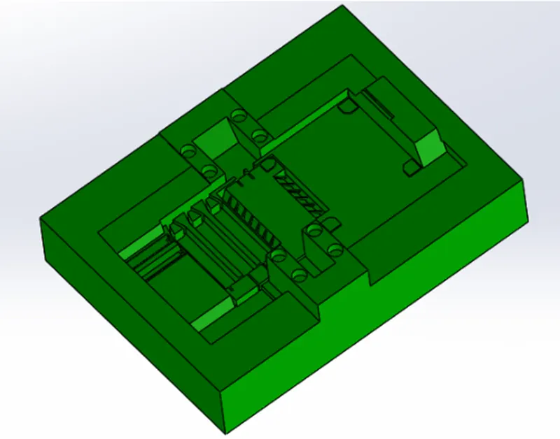
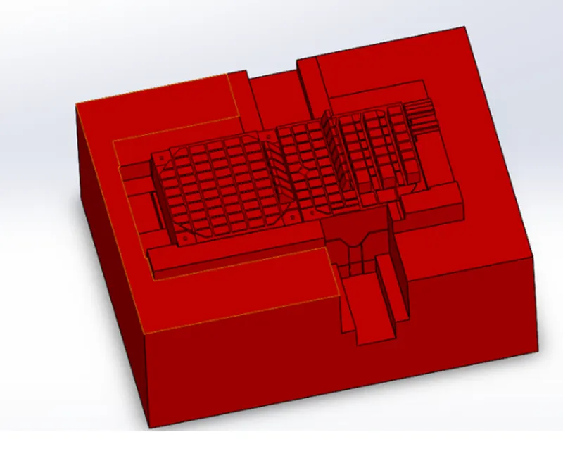
After that add separate part file in assembly named as washer, create a sketch for the washer and extruded option used to make washer. Due to add of washer there will be an intersection in core and cavity block we should remove the intersection material.
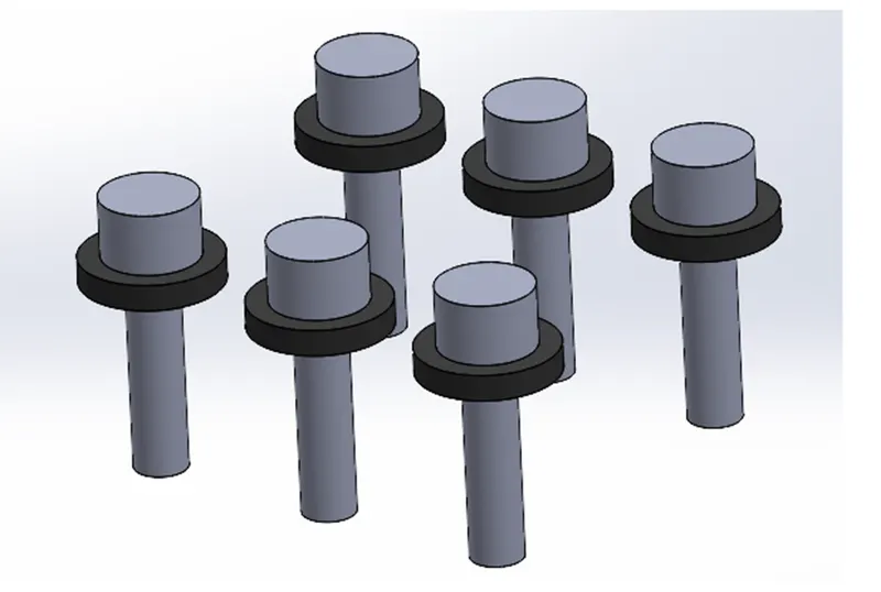
LOCKING MECHANISM- As the slider movement should redistrict, we should create a locking mechanism such that only some distance slider can move for this certain space should be allocated in cavity block that spaced is designed considering the distance for travel of slider.
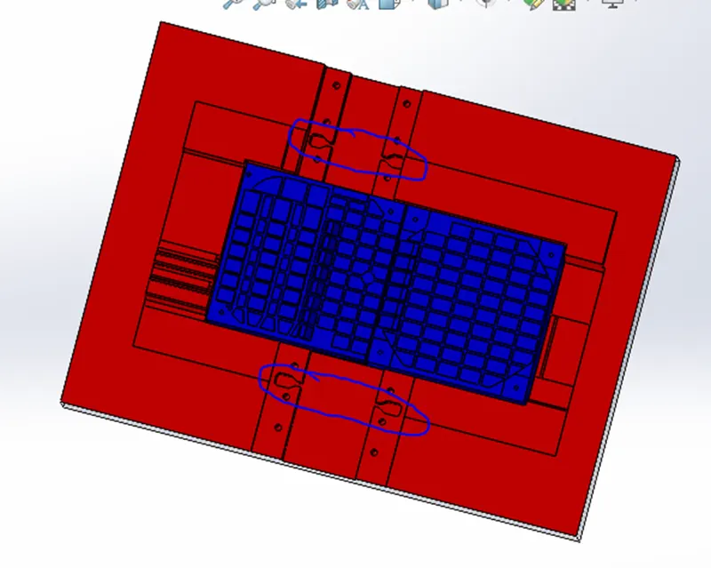
INSERT CREATION-
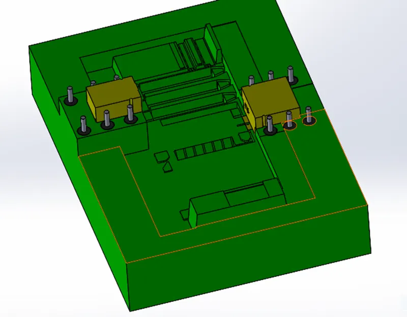
Insert are used when machining of the block is very tough to make .to make this easier insert will be placed where the machining of the block will be tough by creating the split of the block.
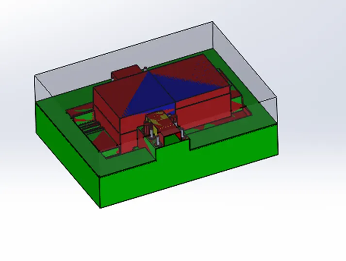
We create a sketch and a plane below the slider surface 20mm.and then split it .we show the blue area where large depth and minimal space where no tool can be machined so here we will create insert.
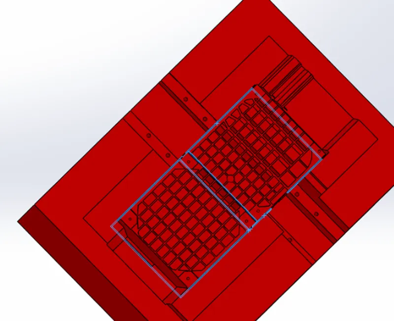
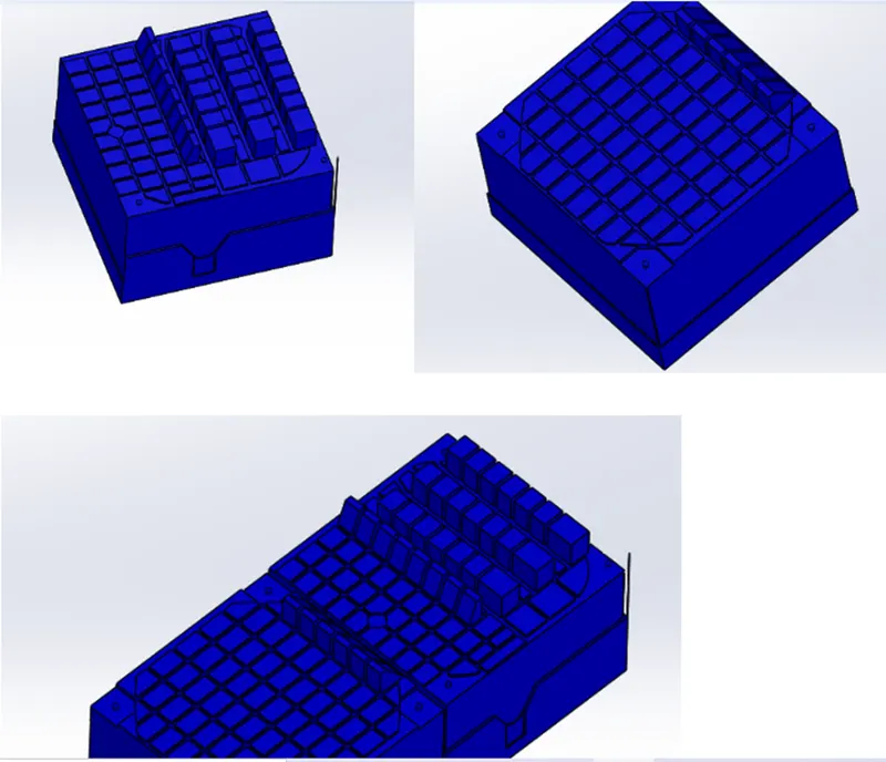
The final assembly of the model after creating slider washer locking mechanism.
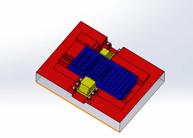
CONCLUSION- The mold for the given model created successfully.