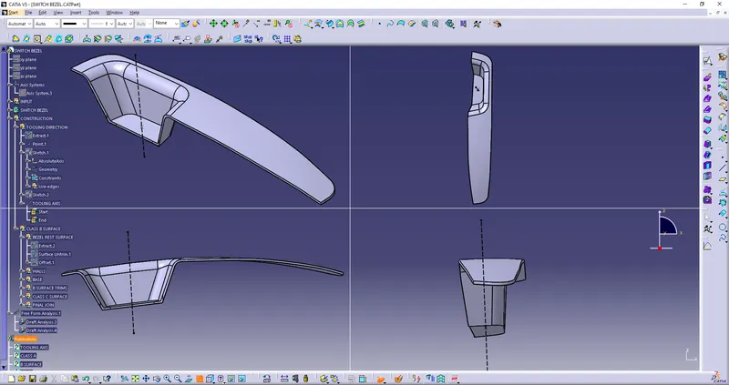
Week 9 - Challenge 2 - Switch Bezel Design
INTRODUCTION
Report on draft analysis and tooling axis creation of a switch bezel.
PROCESS
For draft analysis of any given switch bezel following steps should be taken to successfully complete the analysis of the given task.
Creation of tooling axis
Tooling axis plays the main role in drafting process and it also helps us understand in which direction the tooling is most efficient and economical. In the given design the tooling is created by using sketch and bisecting methods.
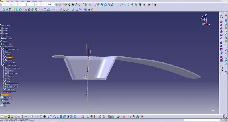
For creating a tooling axis following steps are followed:-
- The base of the bezel is extracted and a point is created on the center of the extracted surface.
- Then an axis system is created on the point.
- A sketches is created and bisection of the class a surface is done on Y direction after that two lines are drawn and their intersection is taken as the first guide for tooling axis.
- On the X direction sketch bisection is done and two lines are drawn at an angle of 6 degree and thus 2nd guide for the tooling axis is created.
- Then both the guide axis 1st and 2nd are bisected to create the main tooling axis.
Drafting and Draft analysis
Drafting is required to allow parts to release or eject from the mold properly and with minimum damage to the core and the product.
Drafting analysis is a process which helps us to test and see if the product and its surfaces are ready for tooling and what is the minimum draft required to obtain the efficient tooling.
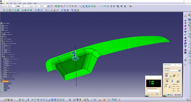
Steps to follow while draft analysis
- Featured draft analysis is the feature which helps us to understand the surfaces are draft ready or not.
- This command is located in the insert menu inside the analysis tab.
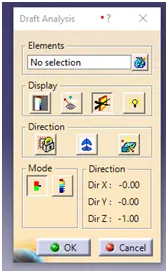
- On opening the command we can obverse a popup of a tool with various option to select from.
-
There are four selection and tools option in the toolbox as element, display, direction and mode.
-
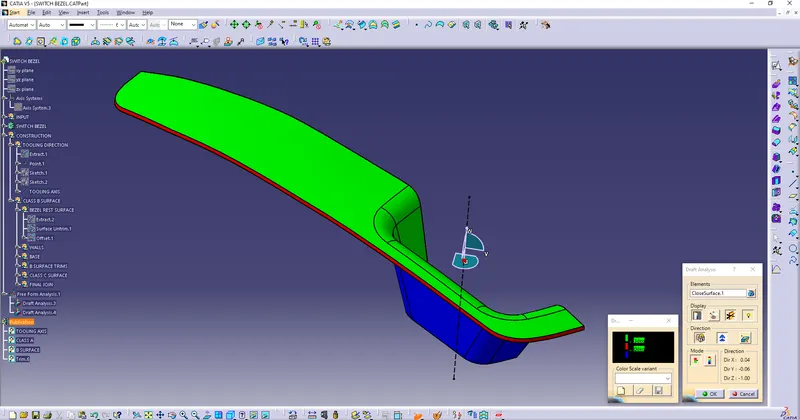
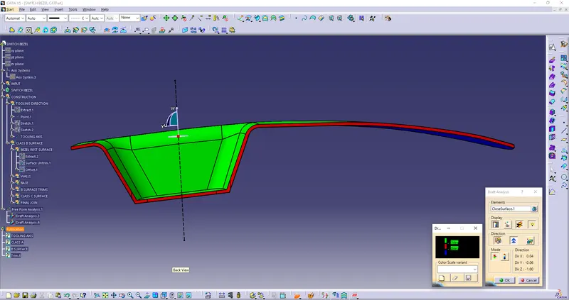
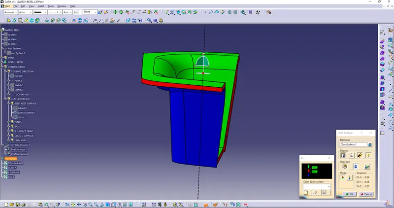
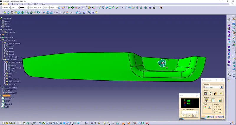
Firstly the compass is dragged and aligned in the tooling axis followed by the lock draft direction command to ensure that the compass doesn’t move.
-
The at any surface the pointer is selected to check weather the component is draft compatible or not.
-
On the display command a tool called color scale helps us to analysis weather the component is draft ready or not.
-
If the surface is in green it clears the minimum first angle, if it is red it means the surface is a zero degree and blue means the draft angle is less the zero degree.
-
-
Conclusion
Drafting of the class a surface is done, the tooling of the class a surface is done and draft analysis is and done.