Week 9 - Challenge 2 - Switch Bezel Design
Aim: Creating the Switch Bezel using the A surface
Procedure:
1) Basic check of boundary.
2) Creating the Tooling Axis.
3) Draft Analysis of Class A surface.
4) Creating the Class B surface
5) Creating the Class C surface
6) Making the close surface after joining all the three surface ( Class A, Class B and Class C)
7) Draft Analysis of the Cclose surface using the tooling axis created before
Input Given:
Class A surface:
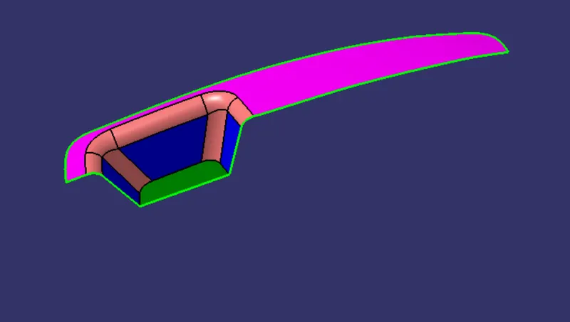
Basic Check:
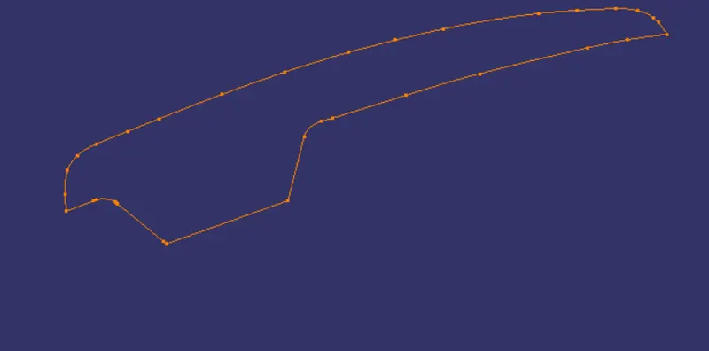
Creation of Tooling Axis:
Tooling axis in Y direction:
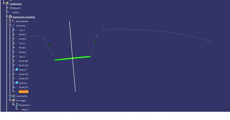
1) We will extract the base plate and will create a point at the center of the surface.
2) Then will be create axis at that point and will construct the sketch using this one plane. in which we will project 3D element in our sketch. The 3d Elements of Class A surface will be our Refence to construct the tooling axis in y direction.
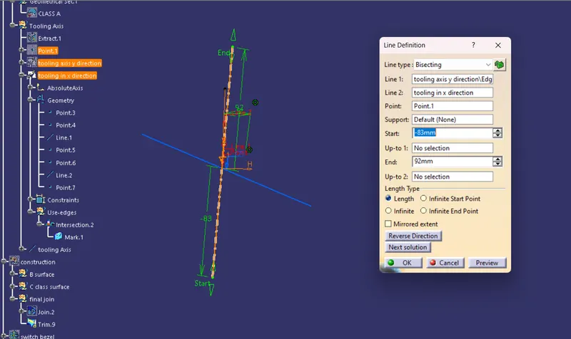
3) There Are two line which are inclined to the surface we will extend them and the line bisecting this two lines will be our tooling axis in y direction
Tooling axis in x direction:
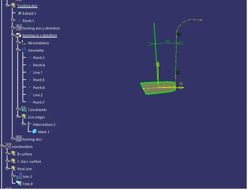
As there is only one side available, so we cannot use the bisecting method to find the tooling axis in x direction.
So we will, create a line at a random angle of 3 degree, because we are suppose to keep the draft of 3 degree and performe the draft anaylsis. Then we are find the one side will not clear the draft analysis so we have to increase the angle to 5 degree and perform the draft analysis again. And this time all the sides will clear the draft analysis and so we can say that this will be the tooling axis in x direction.
Now we will bisect the tooling axis in x and y direction to find the main tooling axis. and point on the base will be our reference point.
Now using this tooling axis we will perform the draft analysis on the class A surface
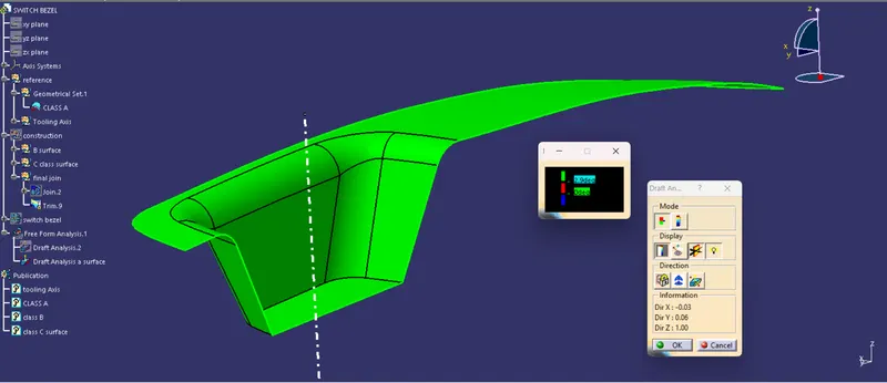
Conclusion of draft analysis:
Green colour indicate that all the side have the angle more then 3 degree and those the class A surface passes the draft analysis
Creation of B surface:
In this challenge we will divede the given part into 3 elements
a) Bezel b) Wall c) Base
The procedure will be the same Extract ----> Offset ----> Untrim ----> Extrapolate ----> Trim
a) Bezel
Extract the bezel from the Class A surface
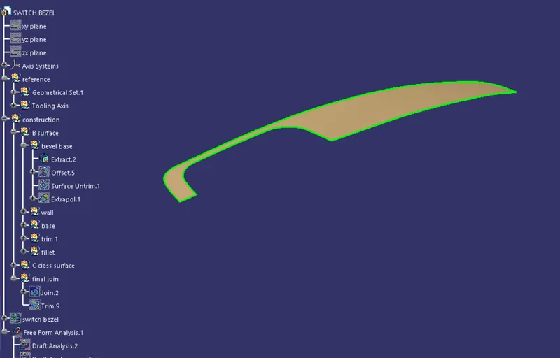
Offset:
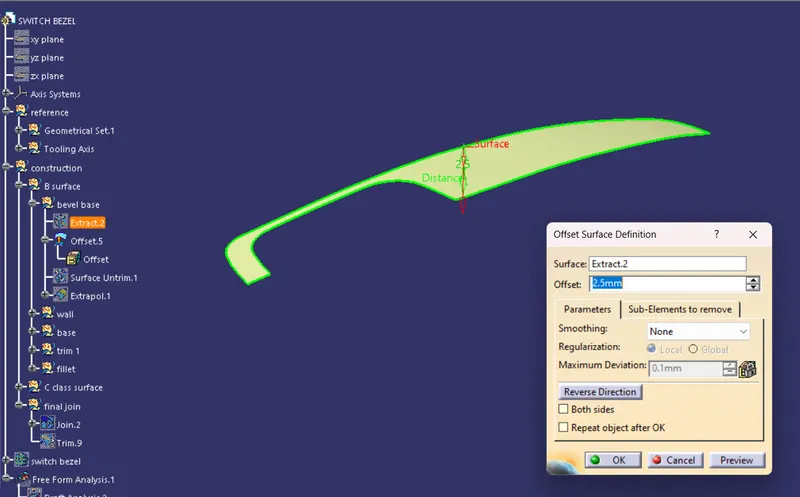
Untrim:
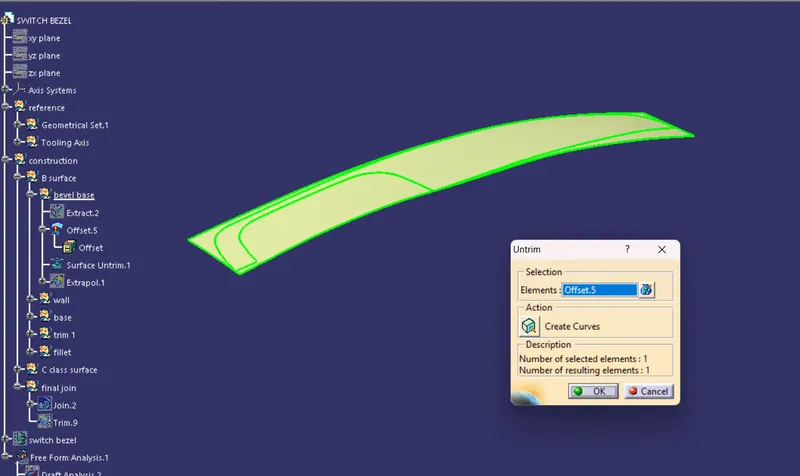
Extrapolate:
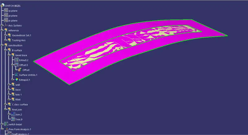
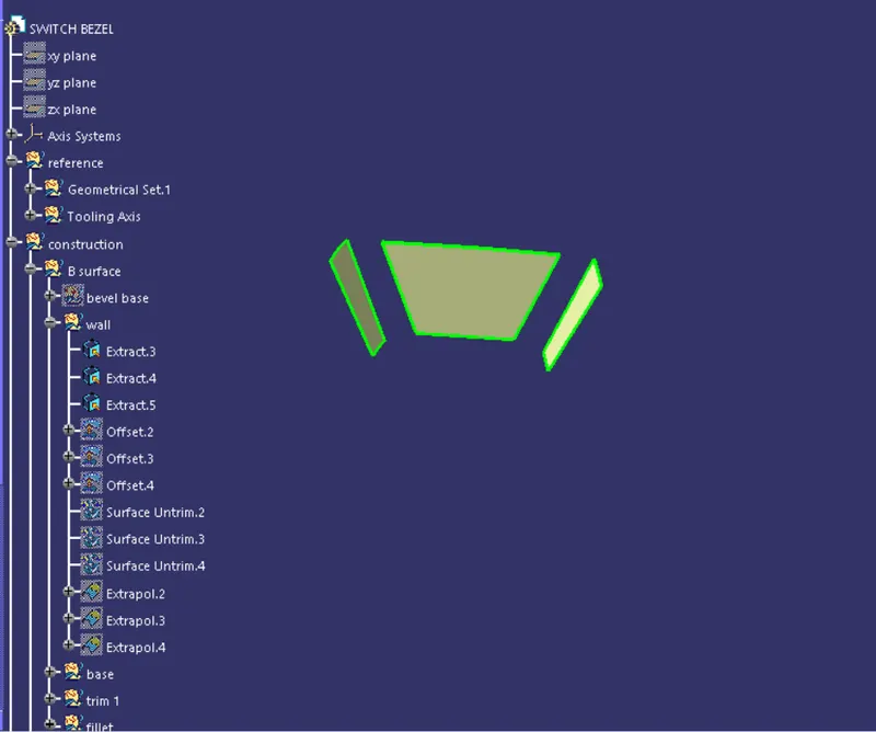
b) Wall
Extract:
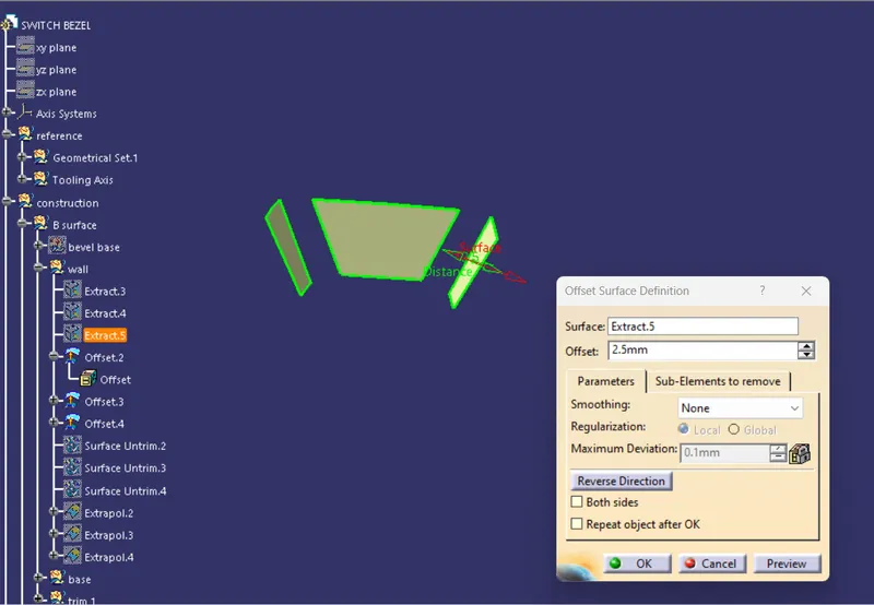
Offset:
Untrim:
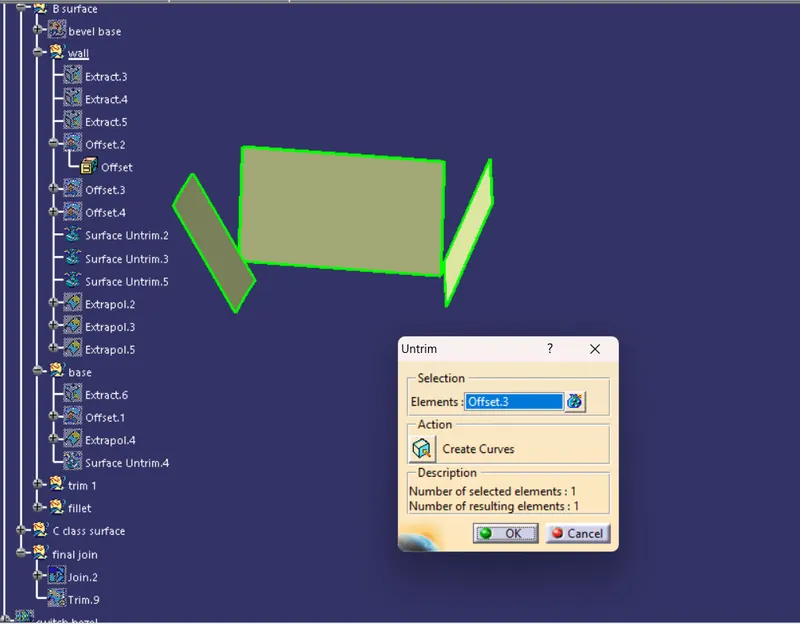
Extrapolate:
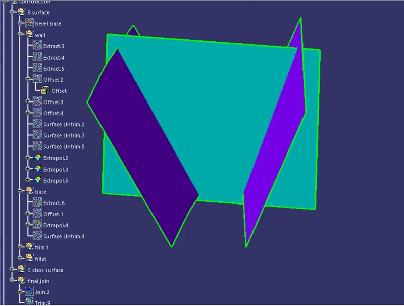
c) Base:
Extract:
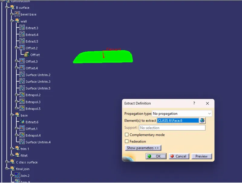
Offset:
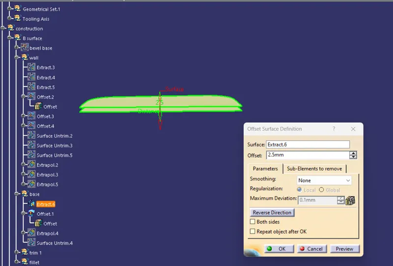
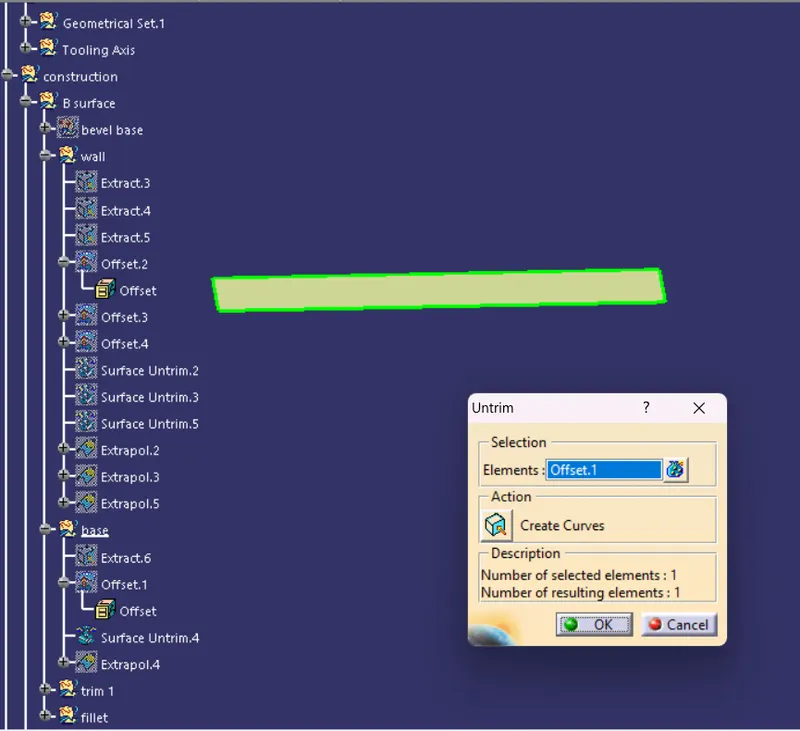
Untrim:
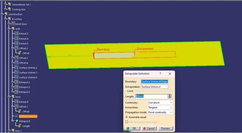
Extrapolate:
Now we will performe the trim for all the elements together
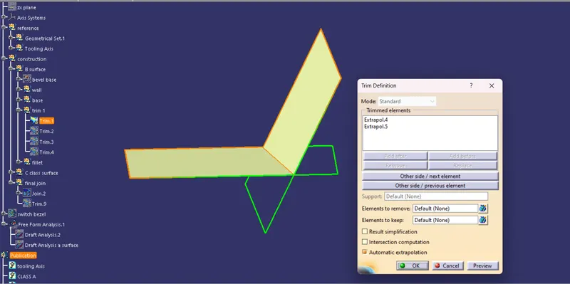
Trim base with Wall:
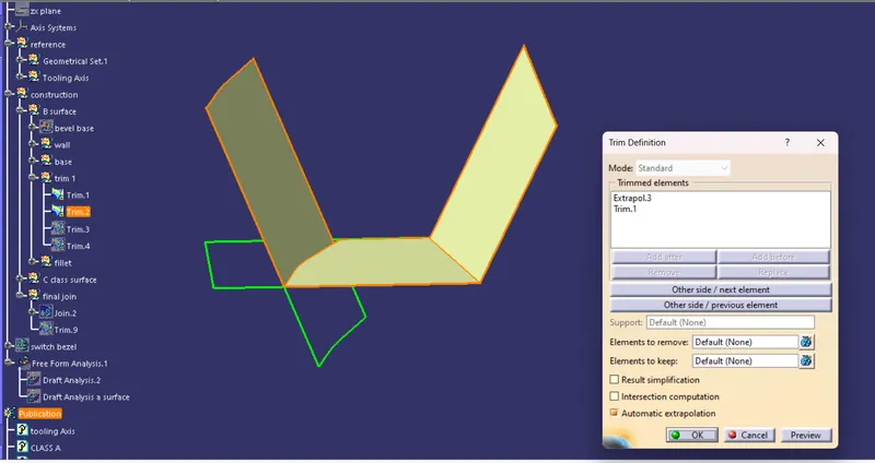
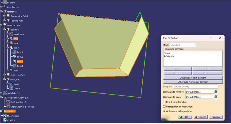
Trim the bezel:

Creation of fillet:
Extract the fillet:
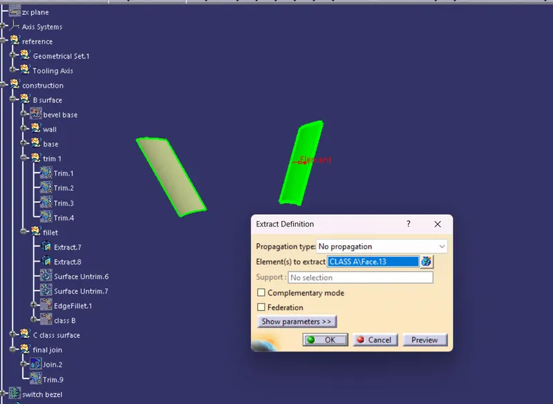
Untrim fillet: to get the proper radius of the fillet
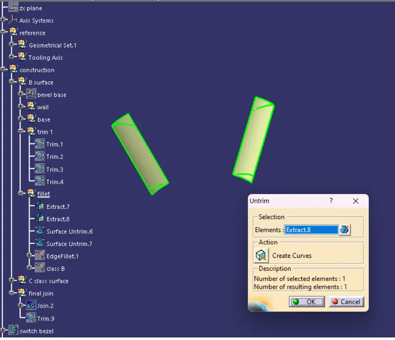
Creation Of Class C surface
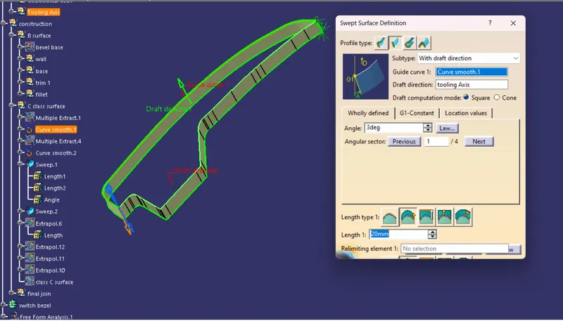
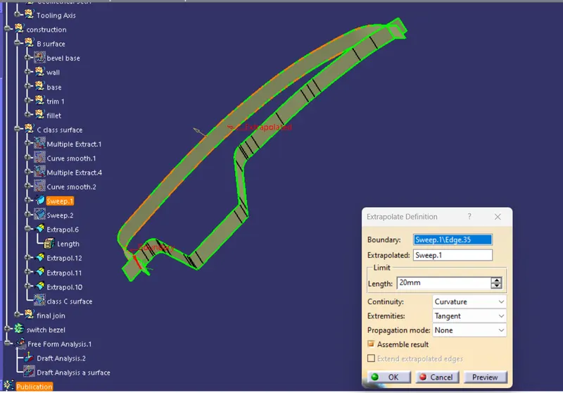
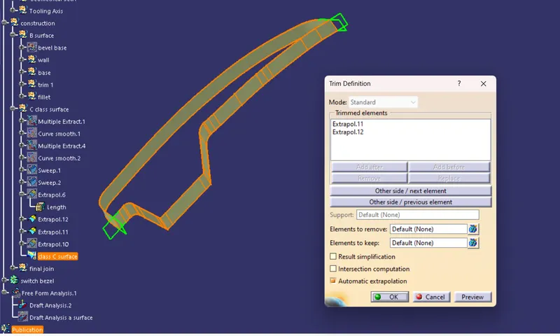
Steps: Boundary ----> Sweep ( along the tooling direction) ----> Extrapolate ----> trim
Boundary: multiple extracting the edges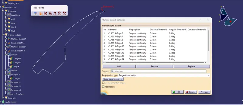
Sweep:
Extrapolate:
Trim:
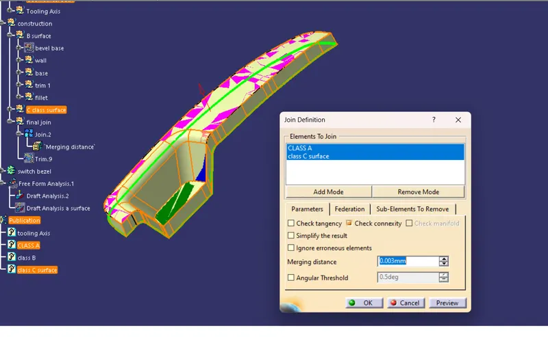
Joining the Class A and Class C surface:
Final trim A and C surface with Class B surface:
Creation On Close Surface:
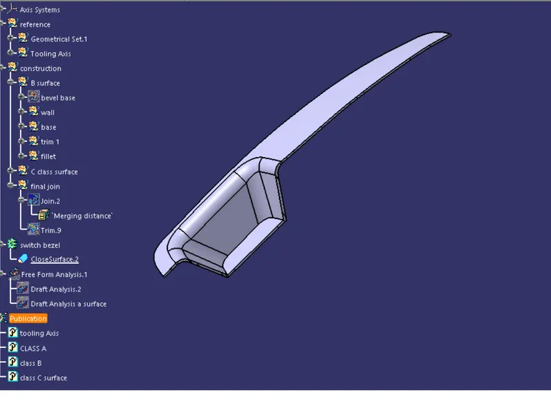
Draft Analysis of the Close surface:
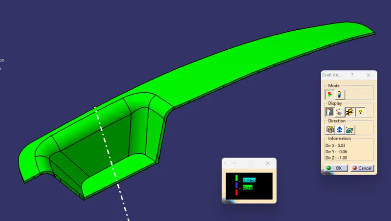
Where the green and red colur intersect there will be the parting line
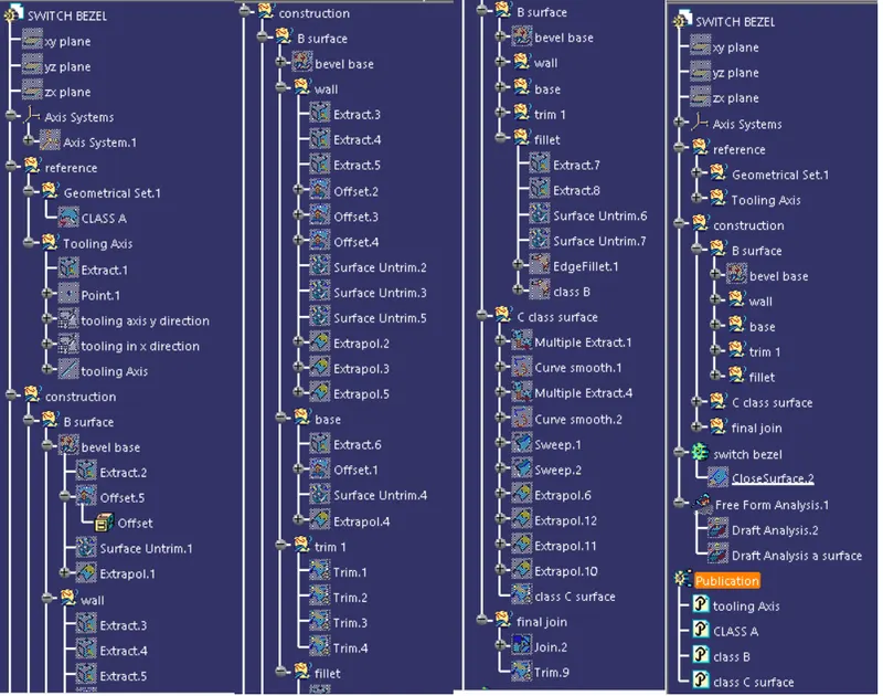
Tree structure:
Conclusion:
In this challenge we have learned how to create the tooling axis when only one side is given and practise all the commands are create the close surface model from a Class A surface