Week 9 - Challenge 2 - Switch Bezel Design
Boundary
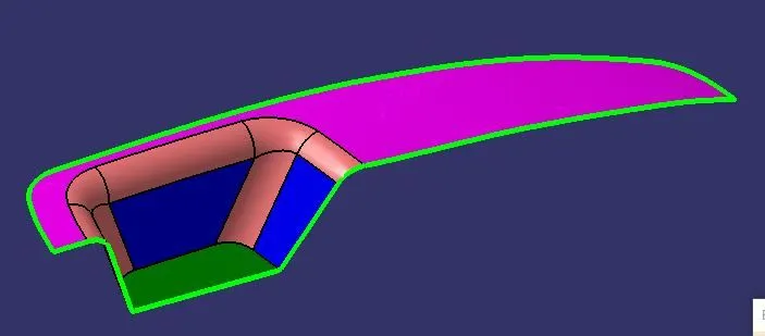
Verify the Class A Surface's connectivity.
Use the connect command to ensure no gaps between the components.
By using the border command or by visually inspecting it, we can check it.
One outside and two inner circular limits make up its three boundaries.
Hence, the initial inspection was finished.
Tooling Axis
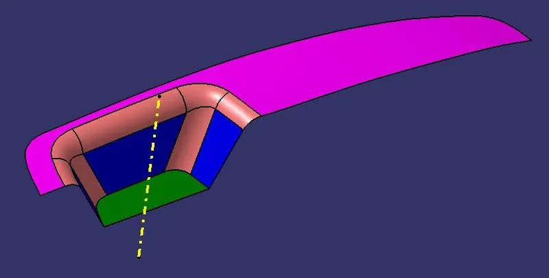
Determine the component's tooling axis. The opening of the cavity or of the mould constitutes the tooling axis.
Look carefully to determine the ideal tooling axis.
Verify each axis.
X is feasible, but it is expensive, and Y is not possible.
The optimal tooling axis is z.
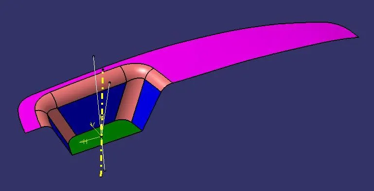
Bisecting Method
To locate the tooling axis the bisecting approach is essentially used. By using the bisecting method, a line is utilised to either cut through the two lines or indicate an error, indicating that the lines are parallel. When a surface intersects a plane, a sketch consisting of two lines is produced. This sketch is then divided into two lines using the bisecting line option, creating a line at the intersection of the two lines. This procedure determines if a given surface is a tool able or not. By utilising the bisecting line option in the line command, we similarly construct tooling clearing axes for x and y that will be utilised to create the primary tooling axis.
Making a tooling axis along the z-axis:
Thus, the z-axis serves as the primary tooling axis.
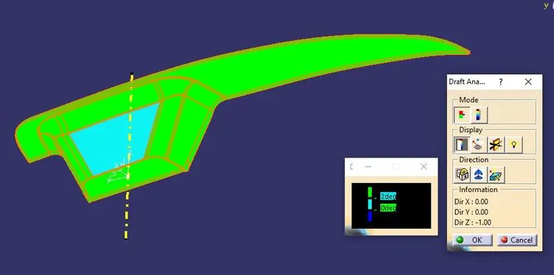
Use the Featured Draft Analysis tool in the tools to now analyse the draft. After locating the compass and aligning it with the tooling axis, click on the lock symbol after aligning, and then click again on the surface after opening the draft analysis toolbox.
Class B Surface
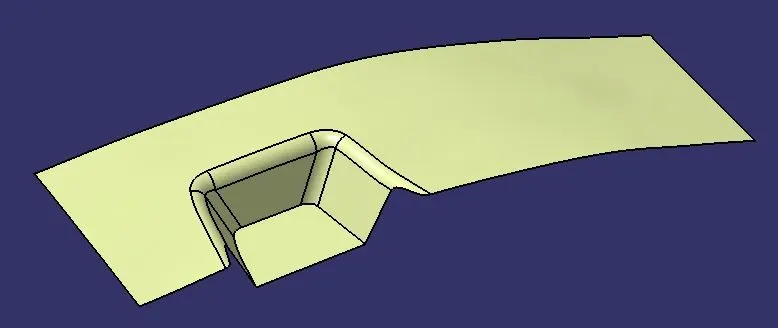
Using the extract option on the Class A surface first extract the walls. Extrapolate is then used to extend the length. Trim the surfaces now to the appropriate surfaces. Then, offset the surface to obtain the necessary thickness.
Similarly, obtain the flat and base surfaces and offset them to the appropriate value.
And now, trim to achieve the desired surface. Fill up the surface now as necessary.
Class C Surface
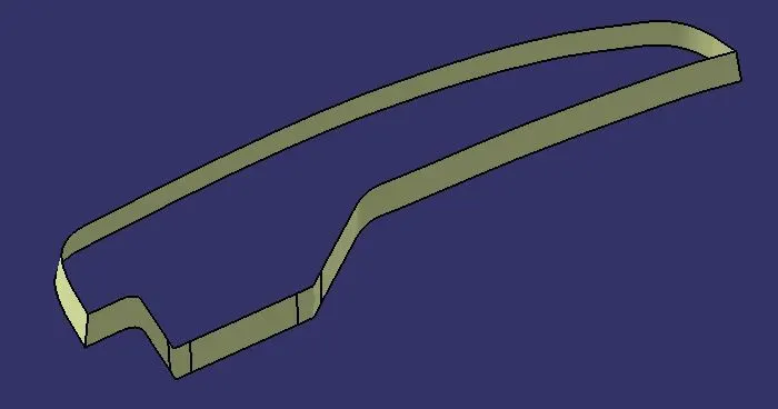
Create boundary of Class_A surface and sweep with draft direction, select tooling axis as direction for the required draft and select the appropriate direction of the draft by selecting the arrows.
And then join the Class_C surface with the Class_A surface later trim the joined surface with the Class_B surface to get the closed surface
after trimming use the closed body command to create a solid part out of the surface.
Draft Analysis of Class A Surface
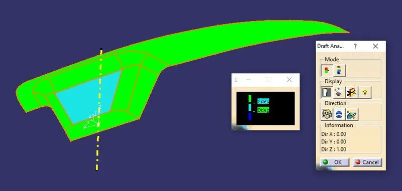
Draft Analysis of Closed Body
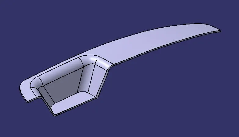
Switch Bezel Iso
Switch Bezel Front
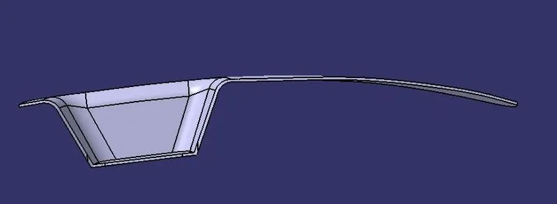
Switch Bezel Side
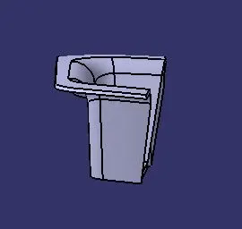
Switch Bezel Top
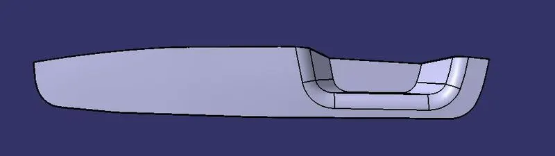
By using the Class A surface a closed body is created by following all the guidelines and by creating Class B and Class C surfaces. Snapshots are attached.